NXR-710
8
MODIFICATION
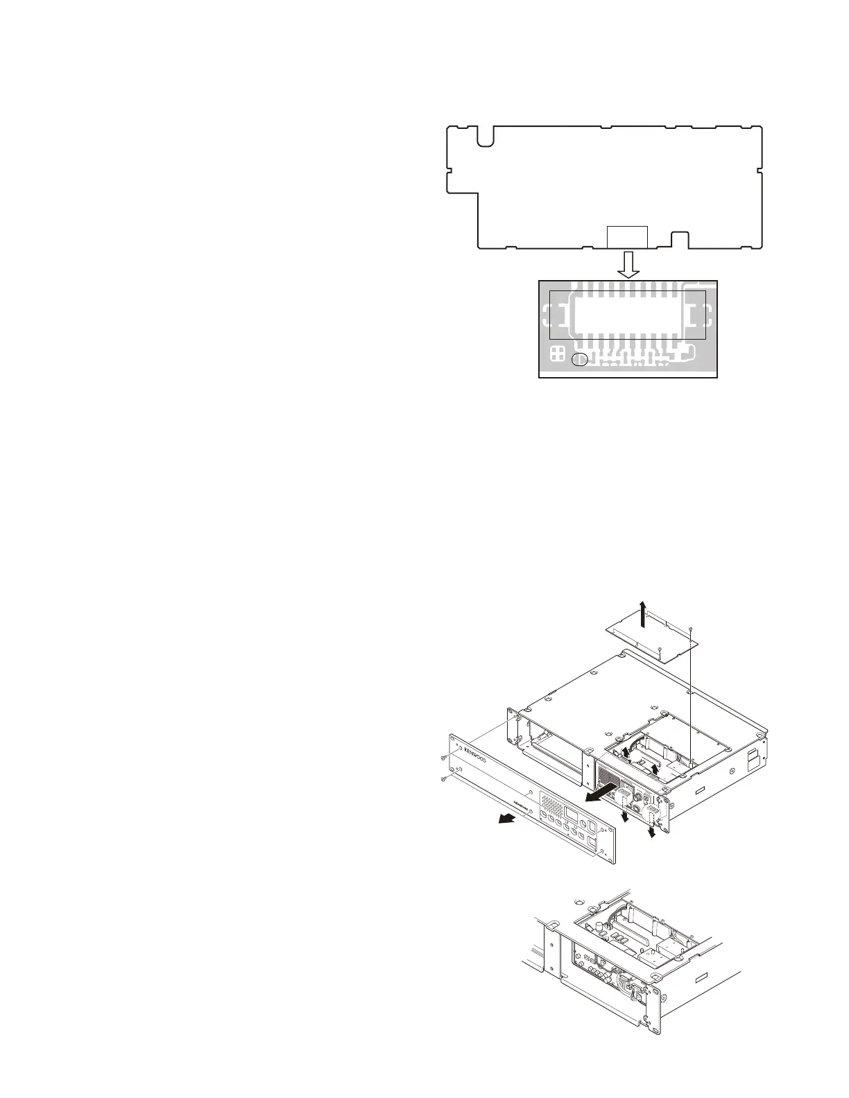
1. DC Source Switch
To prevent the power supply from turning off due to
misoperation of the DC source switch on the front panel or
accidents (tampering) after installation, the main unit can be
kept on regardless of the on/off setting of the DC source
switch on the front panel.
Using solder, short the PSW land near the CN40 connec-
tor.
DISASSEMBLY FOR REPAIR
1. How to Remove the Panel Assy (ABS)
Note: You can remove the panel assembly (ABS) without
removing the top panel (A62-1148-03).
1. To remove the panel (TX-RX,
w
), loosen the 6 screws
(
q
).
2. To remove the panel assembly (Front,
r
), loosen the 6
screws (
e
).
3. The panel assembly (ABS) is securely fastened by 4 tabs
(
t
) on the top and bottom. You can remove the panel
assembly by pulling to the front while you are pulling up
the tabs.
:
@
:
.
.
;
=
=
=
=
CN40
PSW
CONTROL UNIT (X53-4490-10)
Component side
 Loading...