NXR-800
15
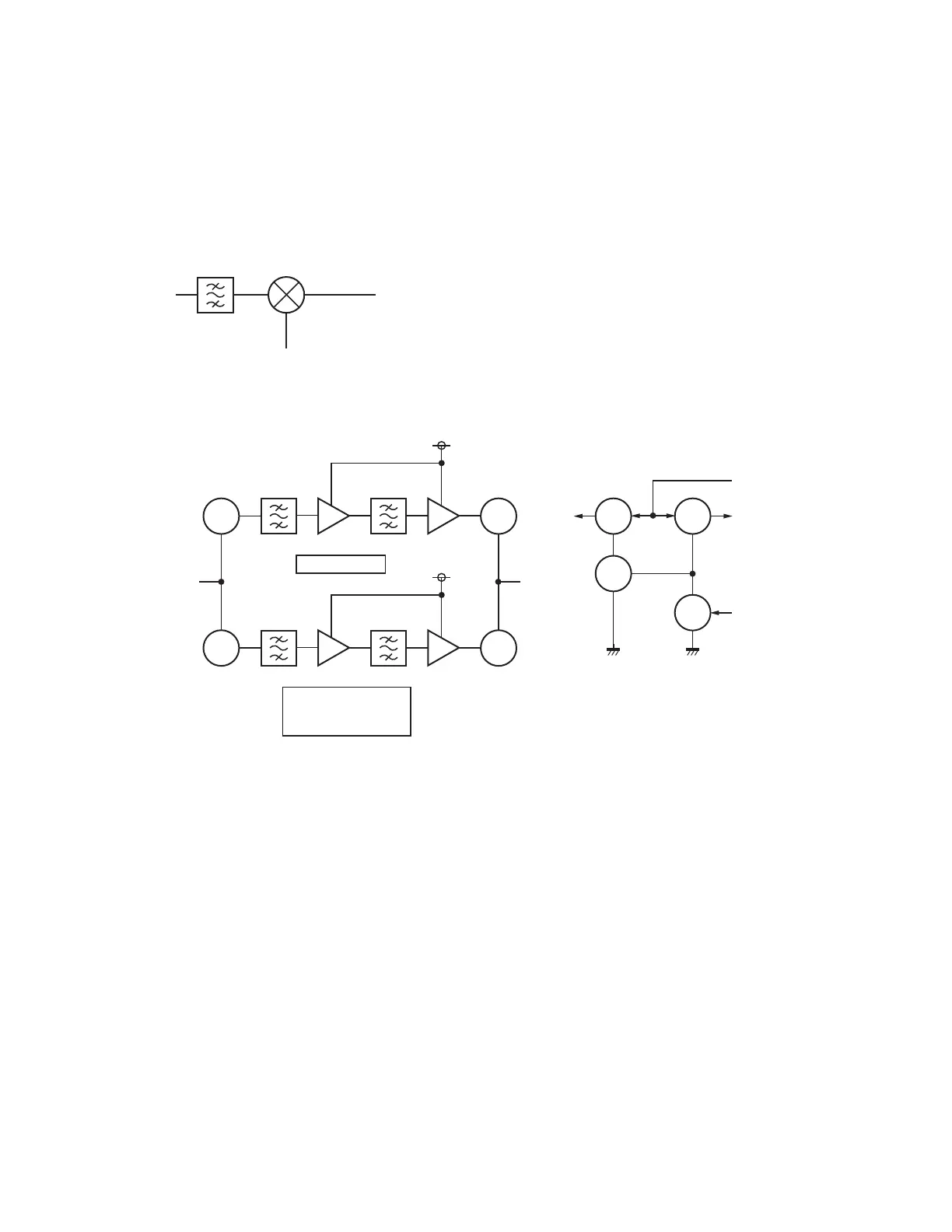
4-2. 1st-Mixer circuit
The unwanted out-of-band RF components produced
by Q1 are attenuated by the BPF. Only the desired signal
is transmitted to the A1 Double Balanced Mixer (DBM).
Here, the desired signal is mixed with the fi rst hetero signal.
49.95MHz is produced as the 1st Intermediate Frequency
(IF1).
BPF
L134,135
A1
Mixer
IF1
49.95MHz
1st local
318.05~350.05MHz
Fig. 17 1st-Mixer circuit
4-3. 1st-IF circuits
The IF1 signal produced by the 1st-Mixer circuit is trans-
mitted through either one of two 1st-IF circuits with differ-
ent bandwidth. The signal passes through the WIDE band
consisting of D9, D22, XF1, Q19, XF3, Q28, D13 and D24
only in Analog_Wide mode. Meanwhile, the signal passes
through the NARROW band consisting of D10, D23, XF2,
Q20, XF4, Q29, D14 and D25 only in Analog_Narrow,
NXDN_Narrow or NXDN_Very-Narrow mode.
XF1 and XF2 is 2 pole and XF3 and XF4 are 4 pole
Monolithic Crystal Filters (MCF). They are BPF for removing
spurious noise occurring close to the desired signal. The
DC switch consists of Q31, Q32, Q26 and Q25, switches the
WIDE and NARROW bands of the 1st-IF circuits.
SW
D9,22
SW
D13,24
D10,23
Q25
SW
Q32
SW
Q31
SW
Q26
SW
L46,52
XF1
L74,90
XF3
Q19 Q28
Analog Wide
8WR
8WR
SW
D14,25
SW
L47,53
XF2
L75,91
XF4
Q20 Q29
Analog Narrow
NXDN Narrow
NXDN Very-Narrow
8NR
8NR
+8V
IF_SW
4-4. Demodulator circuits
The desired signal that passed through the 1st-IF circuits
passes through the distributor consisting of LC parts and is
fed to the IF system IC_IC12, IC13. The signal in Analog_
Wide or Analog_Narrow mode is mixed with the second lo-
cal oscillator hetero signal by the mixer in IC12. 450kHz is
produced as the 2nd Intermediate Frequency (IF2).
It passes through D15, CF2, D16, D19, CF5 and D20
path if the modulation mode is Analog_Wide. It passes
through D15, CF3, D16 and D19, CF7 and D20 path if the
modulation mode is Analog_Narrow. The baseband signal
FM-detected by the quadrature detection circuit consisting
of L128, Q57, and Q58 and is amplifi ed to a signal level of
approximately 100mVrms by IC20 and is then transmitted to
the control unit (X53-413) from CN42 (pin 12).
The signal in NXDN_Narrow or NXDN_Very-Narrow
mode is mixed with the second local oscillator hetero signal
by the mixer in IC13. 450kHz is produced as the 2nd Inter-
mediate Frequency (IF2). Here, irrespective of modulation
modes, it passes through the CF4 and CF6 path. It is trans-
mitted as the baseband signal via IC14 to the CN43 control
unit, X53-414.
CF2, CF3, CF4, CF5, CF6 and CF7 are hexode Ceramic
Filters. They are BPF for removing spurious noise occurring
close to the desired signal.
Fig. 18 1st-IF circuits
CIRCUIT DESCRIPTION

 Loading...