Do you have a question about the Kenwood NX-210 and is the answer not in the manual?
| Operating Temperature | -30°C to +60°C |
|---|---|
| IP Rating | IP54 |
| Frequency Range | 136-174 MHz |
| Power Output | 5 W |
| Channel Spacing | 12.5 / 25 kHz |
| Digital Standards | NXDN |
Covers manual scope, intended audience, and procedures for ordering replacement parts.
Essential safety precautions and notes on transceiver serviceability.
Diagram illustrating the steps for setting up the transceiver based on configuration.
Describes the different operational modes available for the transceiver.
Instructions for entering modes and references to panel test/tuning modes.
Covers PC mode setup, connection, interface, and software descriptions.
Introduction to firmware programming and its preface.
Steps for connecting, programming, and understanding firmware functions.
Procedure for cloning transceivers, including password entry and limitations.
Step-by-step guide for installing the optional VGS-1 unit.
Precautions during cover removal and component handling for installation.
Includes waterproof, general disassembly, and reassembly precautions.
Detailed steps for removing TX-RX unit and top packing.
Procedures for inserting rubber spacer and mounting chassis onto case.
Steps for removing and installing the lithium cell.
Procedure for forming Cord ASSY and correspondence for case replacement.
Information on changing reusable and non-reusable parts during assembly.
General description of transceiver operation and frequency setup.
Details on the receiver's RF and IF signal paths.
Explanation of audio processing, speaker switching, and squelch circuit.
Details on the transmitter's audio band and base band signal processing.
List of components for the display unit.
List of components for the TX-RX unit.
Continuation of component descriptions for the TX-RX unit.
Detailed parts list for the main unit and display unit.
Continuation of parts list for the display unit.
Detailed parts list for the TX-RX unit.
Continuation of the parts list for the TX-RX unit.
Flowchart for diagnosing BGA IC issues when the transceiver doesn't power on.
Procedures for checking power supply voltages and clock signals.
Procedures for checking control signals to/from ASIC and ASIC output signals.
Troubleshooting LCD display errors like "INIT ERROR" related to ASIC, DSP, or SRAM.
Steps to follow after replacing the printed circuit board, including firmware updates.
Notes on NXDN Trunking ESN changes and Kenwood ESN updates.
Overview of transceiver controls and features of the panel test mode.
Describes key operations, LED/LCD indicators, and LCD display in test mode.
Details analog/NXDN signaling, panel tuning procedures, and frequency tables.
Detailed descriptions of various adjustment items and their relevance.
Terminal functions for the Display unit (CN3, CN8) and TX-RX unit (CN201).
Pin functions for various connectors including CN313, CN336, CN337, and CN804.
Terminal functions for solder pads and the Option board unit's CN923.
Detailed pinout and rating conditions for the universal connector.
Component and foil side views of the display unit PC board with component placement.
Component and foil side views of the TX-RX unit PC board.
Schematic diagram of the display unit.
Schematic diagram of the TX-RX unit.
Block diagram of the TX-RX unit, showing major functional blocks.
Block diagram of the display unit and its connections.
Level diagrams for receiver and transmitter sections showing signal levels.
Details, external views, and schematic diagrams for battery packs.
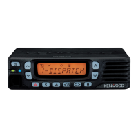
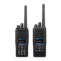
General specs: frequency range, channels, zones, voltage, battery life, dimensions, weight.
Receiver specs: sensitivity, selectivity, intermodulation, spurious response, audio.
Transmitter specs: RF power, spurious response, hum/noise, audio distortion, modulation.