EasyManua.ls Logo

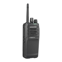
Kenwood NX-340 User Manual

Kenwood NX-340
44 pages
To Next Page IconTo Next Page
Page #1 background imageLoading...
Page #1 background image
SERVICE MANUAL
COPYRIGHT © 2014 JVC KENWOOD Corporation
No.RA003<Rev.004>
2014/12
B5B-7102-20
UHF DIGITAL TRANSCEIVER
RA003<Rev.004>201412SERVICE MANUALB5B-7102-20
NX-340, NX-340(U)
COPYRIGHT © 2014 JVC KENWOOD Corporation
Note :
Lead free solder used in the board (material : Sn, Ag, In, Bi, melting point : 227 Centigrade)
TABLE OF CONTENTS
1 PRECAUTION. . . . . . . . . . . . . . . . . . . . . . . . . . . . . . . . . . . . . . . . . . . . . . . . . . . . . . . . . . . . . . . . . . . . . . . . . 1-4
2 SPECIFIC SERVICE INSTRUCTIONS . . . . . . . . . . . . . . . . . . . . . . . . . . . . . . . . . . . . . . . . . . . . . . . . . . . . . . 1-4
3 DISASSEMBLY . . . . . . . . . . . . . . . . . . . . . . . . . . . . . . . . . . . . . . . . . . . . . . . . . . . . . . . . . . . . . . . . . . . . . . 1-13
4 ADJUSTMENT . . . . . . . . . . . . . . . . . . . . . . . . . . . . . . . . . . . . . . . . . . . . . . . . . . . . . . . . . . . . . . . . . . . . . . . 1-16
5 TROUBLESHOOTING . . . . . . . . . . . . . . . . . . . . . . . . . . . . . . . . . . . . . . . . . . . . . . . . . . . . . . . . . . . . . . . . . 1-20
This service manual has been revised due to the addition of NX-340 type K3
REVISED
T
his product complies with the RoHS directive for the European market.
This product uses Lead Free solder.

Table of Contents

Question and Answer IconNeed help?

Do you have a question about the Kenwood NX-340 and is the answer not in the manual?

Kenwood NX-340 Specifications

General IconGeneral
BrandKenwood
ModelNX-340
CategoryTwo-Way Radio
LanguageEnglish

Summary

Specification

General Specifications

General specifications including frequency range, voltage, and dimensions.

Receiver Specifications

Specifications for the receiver section, including sensitivity and audio output.

Specific Service Instructions

Circuit Description Overview

Detailed explanation of the transceiver's internal circuits and their functions.

Frequency Configuration

Explanation of frequency generation and configuration within the transceiver.

Receiver System Details

Description of the receiver system, including RF amplifier and mixer stages.

Transmitter System Details

Description of the transmitter system, including microphone and final amplifier circuits.

Frequency Synthesizer Unit

Explanation of the frequency synthesizer, including TCXO, VCO, and PLL-IC.

Control Circuit Overview

Overview of the MCU and peripheral circuits controlling transceiver functions.

Signaling Circuit Details

Details on the signaling circuit for encoding and decoding data like QT/DQT.

Power Supply System

Description of the power supply system and its various voltage outputs.

Disassembly Procedures

Disassembly Precautions

Important safety and handling precautions before disassembling the unit.

Reassembly Precautions

Important precautions to follow during the reassembly process.

Adjustment Procedures

Test Equipment for Alignment

List of essential test equipment and their specifications for calibration.

Frequency and Signaling Adjustment

Procedures for adjusting frequency and signaling parameters.

Transmitter Section Adjustments

Adjustment procedures specific to the transmitter section.

Receiver Section Adjustments

Adjustment procedures specific to the receiver section.

Troubleshooting and Realignment

Realignment Procedures

Procedures for realigning the transceiver's functions.

Schematic Diagram

Block Diagram

Related product manuals