Do you have a question about the Kenwood NX-820H and is the answer not in the manual?
| Power Output | 5W |
|---|---|
| Operating Temperature | -30°C to +60°C |
| Digital Protocol | NXDN |
| GPS | Optional |
| Bluetooth | No |
| IP Rating | IP54/55 |
| Battery Life | 14 hours |
| Zones | 16 zones |
| Channel Spacing | 12.5 kHz / 25 kHz |
| Channel Capacity | 260 |
Describes the manual's purpose, part ordering, and safety precautions.
Outlines steps before unit installation.
Covers radio placement, DC power, and antenna system.
Lists and describes different operational modes (User, PC, Clone, etc.).
Explains how to access various transceiver modes.
Details steps for entering and using panel test mode.
Explains PC connection, interface cables, and programming software.
Outlines the process for updating transceiver firmware.
Describes transferring data between transceivers.
Details the KCT-60 connection cable kit.
Explains horn alert and ignition sense functions.
Details the KES-5 external speaker connection.
Covers serial port level and signal type changes.
Covers cabinet and panel removal procedures.
Details removing the TX-RX PCB and related components.
Discusses reassembly steps and LED handling.
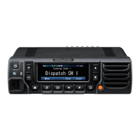
Introduces the unit and its operating frequencies.
Describes the receiver RF and IF stages.
Details audio, squelch, transmitter, and PLL circuit blocks.
Explains power supply, signaling, compander, and GPS sections.
Details components used in the display unit.
Lists components found on the TX-RX unit.
Lists components for the display unit.
Lists components for the TX-RX unit.
Illustrates the assembly of the display unit.
Shows the exploded view of the TX-RX unit.
Shows the packaging of included accessories.
Illustrates how the main transceiver unit is packed.
Focuses on diagnosing problems with BGA integrated circuits.
Details checks for power, clock, and reset signals.
Covers ASIC output, panel control, and error displays.
Guides GPS troubleshooting and TX-RX unit replacement.
Covers ESN confirmation, data writing, and label attachment.
Explains how to enter and use the panel test mode.
Details frequency settings and analog mode signaling parameters.
Covers tuning modes and reference level frequency adjustments.
Details maximum deviation and signaling tone adjustments.
Covers AF level, RSSI, and squelch adjustments.
Details the specifications for alignment test gear.
Describes essential connection cables for testing.
Outlines steps for frequency, power, and sensitivity checks.
Covers general settings, receive/transmit assist, and sensitivity.
Details pin assignments and functions for both units.
Provides detailed specifications for key connectors.
Shows component placement for the display unit.
Illustrates component placement for the TX-RX unit.
Shows the primary connection between the display and TX-RX units.
Details the electronic schematics for the TX-RX unit.
Illustrates the interconnections between major functional units.
Shows typical signal levels for RF, IF, and AF stages.
Provides specifications for the KRA-40 GPS antenna.
Lists general operating parameters like frequency range and voltage.
Details receiver sensitivity and transmitter RF power.