EasyManuals Logo

Kenwood R-5000 Instruction Manual

Kenwood R-5000
36 pages
To Next Page IconTo Next Page
To Previous Page IconTo Previous Page
Page #4 background imageLoading...
Page #4 background image
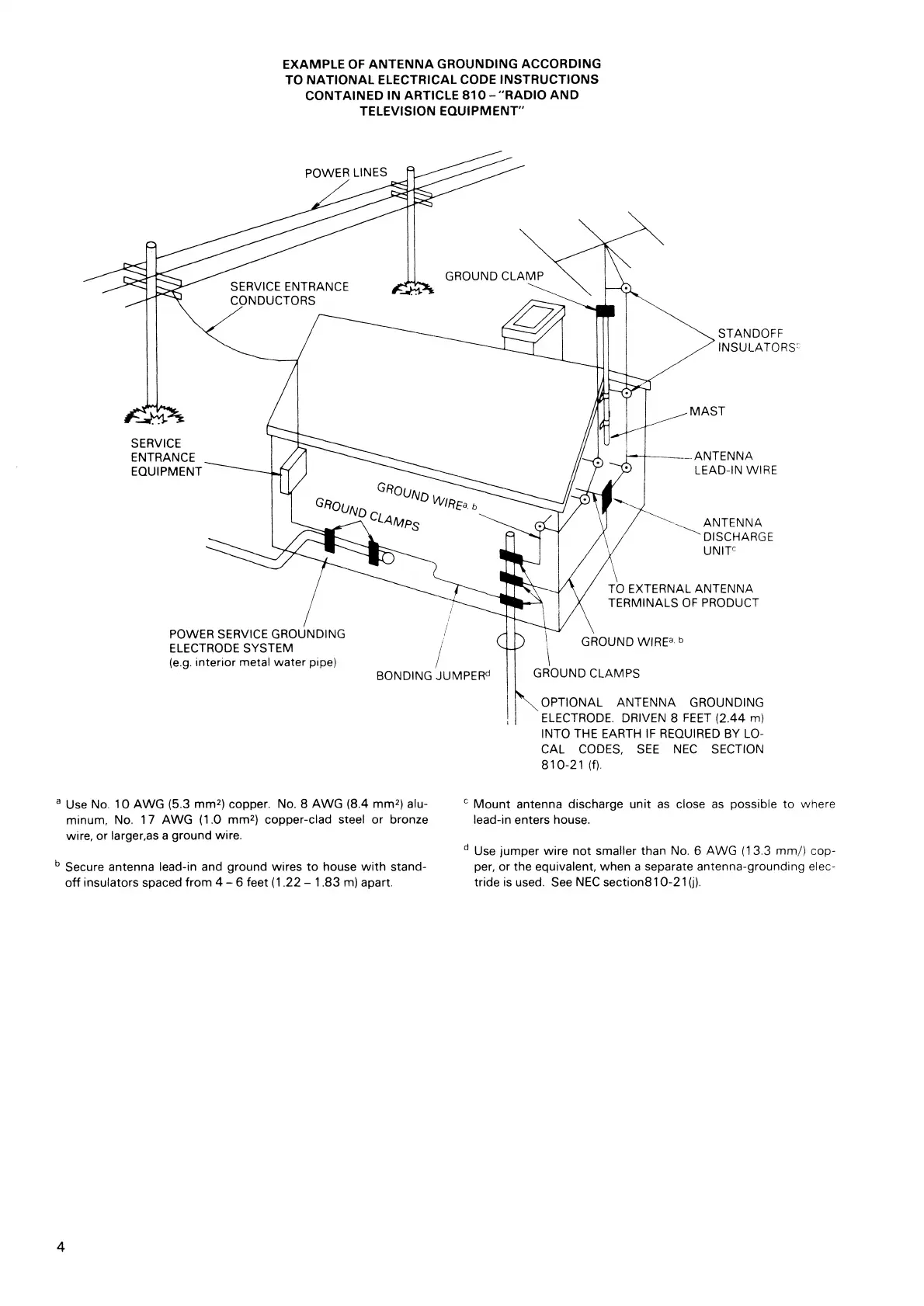
EXAMPLE OF ANTENNA GROUNDING ACCORDING
TO NATIONAL ELECTRICAL CODE INSTRUCTIONS
CONTAINED IN ARTICLE 810 –"RADIO AND
TELEVISION EQUIPMENT"
a
Use No. 10 AWG (5.3 mm
2
) copper. No. 8 AWG (8.4 mm
2
) alu-
C
Mount antenna discharge unit as close as possible to where
minuet, No. 17 AWG (1.0 mm
2
) copper-clad steel or bronze
lead-in enters house.
wire, or larger,as a ground wire.
d
Use jumper wire not smaller than No. 6 AWG (13.3 mm/) cop-
b
Secure antenna lead-in and ground wires to house with stand-
per, or the equivalent, when a separate antenna-grounding elec-
off insulators spaced from 4 – 6 feet (1.22 –1.83 m) apart.
tride is used. See NEC section810-21(j).
4

Other manuals for Kenwood R-5000

Questions and Answers:

Question and Answer IconNeed help?

Do you have a question about the Kenwood R-5000 and is the answer not in the manual?

Kenwood R-5000 Specifications

General IconGeneral
ModesAM, FM, SSB, CW
Impedance50 ohms
Frequency stability±100 Hz
Memory Channels100
Sensitivity0.5 μV (SSB)
Selectivity6 kHz (AM)
Power Supply13.8 V DC
Image rejection70 dB
IF rejection80 dB
Output1.5W at 8 ohms

Related product manuals