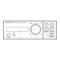
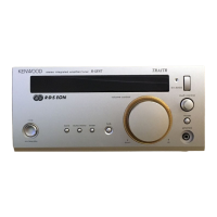
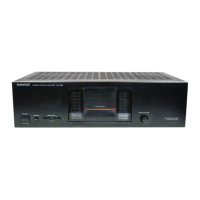
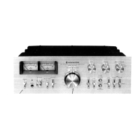
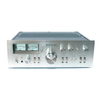
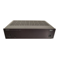
R-A100/A150/V300/V350
8
CIRCUIT DESCRIPTION
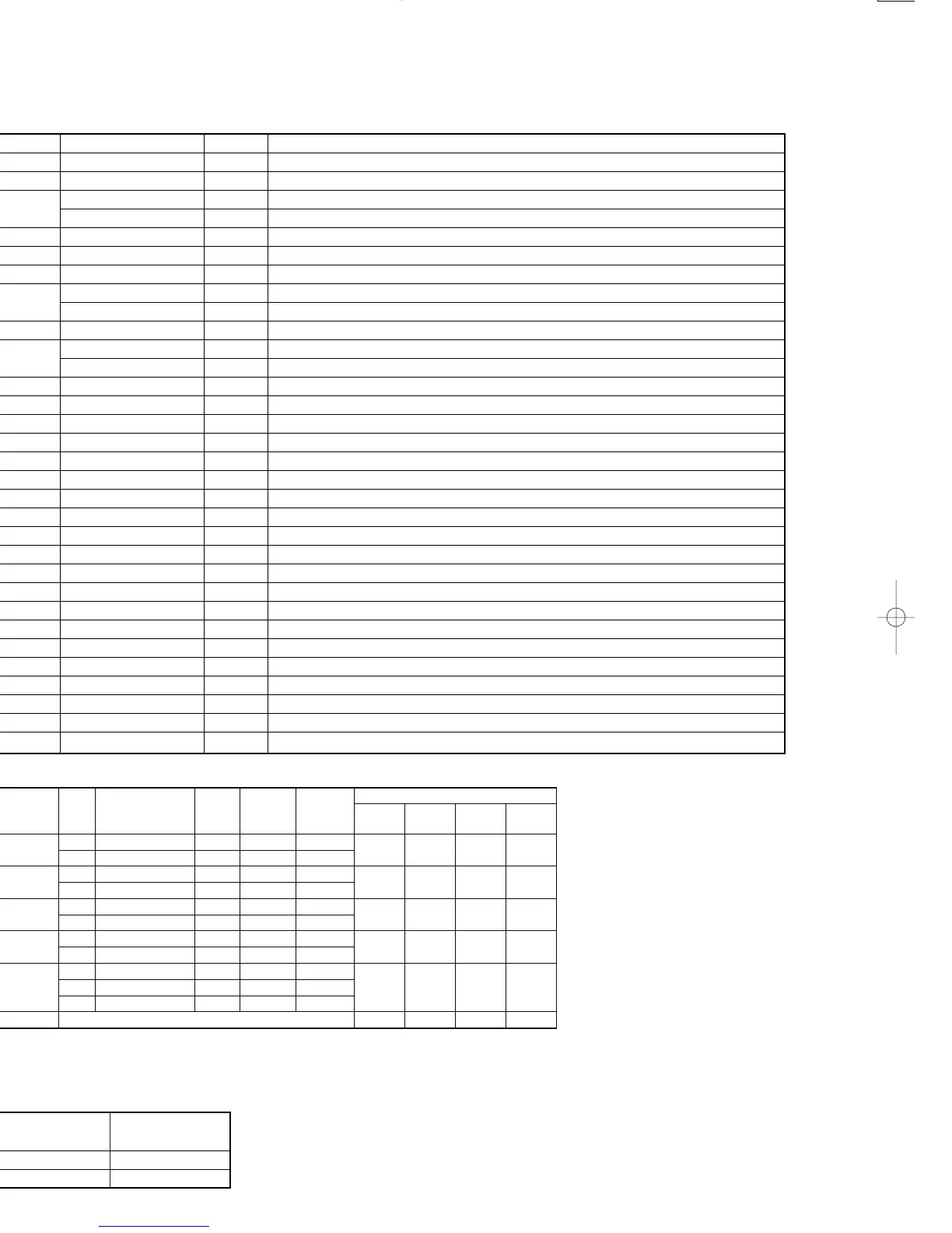
No. Name I/O Description
41 +10dB_ATT O +10Db attenuator L: ATT ON
42 VOL_DATA I/O Electric volume control data
43 TAP O LO-HI tap change-over R-V300/V350
VCR_REC O VCR REC change-over R-A100/A150
44,45 N.C. I No used
46 Vdd - Power supply(+5V)
47,48 N.C. I No used
49 CS_RELAY O Center and surround speaker relay control L: C,Sch OFF R-V300/V350
I NPUT LEVEL O Input level change-over H: 0dB R-A100/A150
50 F_RELAY O Front speaker relay control L: L,Rch OFF
51 TC9215 O Vidual selector change-over R-V300/V350
TAPE1_REC O TAPE! REC change-over R-A100/A150
52 VOICE_CTRL O Voice activation / Standby LED
53 SEL_STB1 O Strobe signal for selector IC
54 SEL_DATA O Data signal for selector IC
55 SEL_CLK O Clock signal for selector IC
56 VOICE I Input port of voice activation
57 VOL_CLK O Clock signal for electric volume
58,59 N.C. I No used
60 REM_REWRREQ O Rewrite request signal of interlocution remocon data
61 REM_RWR I Rewrite in signal of interlocution remocon data
62 REM_REREN I Transmit signal of interlocution remocon data L: Transmission
63-70 INP 0-7 O Remote control data bits 0-7
71 VSEL1 O Vidual selector
72 POWER O Power relay control
73-78 SEG11-16 O Display segment control 11-16 / Key scan 0-5
79 Vload - Connect to PLL down resistor
80 SEG10 O Display segment control 10
81 SEG9 O Display segment control 9 / Key scan 7 8Tuner destination)
82 SEG8 O Display segment control 8 / Key scan 8 (Model discrimination)
83-89 SEG1-7 O Display segment control 1-7
90-100 GRID1-11 O Display grid control 1-11
Diode SW(DSWx) 0=No diode (Static mode,LOW)
1=Diode (Static mode,HIGH)
X=Transistor SW (0=OFF / 1=ON)
2-5 MODEL DISTINATION
MODEL
DIODE SW
(X14)D34
R-V300/V350 0
R-A100/A150 1
 Loading...