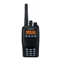
Do you have a question about the Kenwood TK-3170 and is the answer not in the manual?
| frequency range | 450~490MHz (K, K4) 440~480MHz (M) 400~430MHz (K3, K6, M3) |
|---|---|
| number of channels | Max. 128 per radio |
| zone channels | Max. 128 per zone |
| trunking GID | Max. 250 per zone |
| channel spacing (wide) | 25kHz |
| channel spacing (narrow) | 12.5kHz |
| battery voltage | 7.5V DC ± 20% |
| operating temperature range | –22°F~+140°F (–30°C~+60°C) |
| frequency stability | ± 0.00025% (–22°F~+140°F) |
| antenna impedance | 50Ω |
| channel frequency spread (K,K4,M) | 40MHz |
| channel frequency spread (K3,K6,M3) | 30MHz |
| KNB-24L (1400mAh) | 9 hours |
|---|---|
| KNB-25A (1200mAh) | 8 hours |
| KNB-26N (2000mAh) | 12 hours |
| KNB-35L (1950mAh) | 11 hours |
| sensitivity (wide) | 0.25µV |
|---|---|
| sensitivity (narrow) | 0.28µV |
| selectivity (wide) | 70dB |
| selectivity (narrow) | 65dB |
| intermodulation distortion (wide) | 65dB |
| intermodulation distortion (narrow) | 60dB |
| spurious response | 65dB |
| audio output | 500mW with less than 10% distortion |
| RF power output (HI) | 4W |
|---|---|
| RF power output (LO) | 1W |
| spurious response | 70dB |
| modulation (wide) | 16K0F3E |
| modulation (narrow) | 11K0F3E |
| FM hum & noise (wide) | 45dB |
| FM hum & noise (narrow) | 43dB |
| audio distortion | Less than 5% |
| dimensions with KNB-24L or 35L battery | 2-7/32 x 4-9/32 x 1-1/4 in. (56 x 109 x 31.7 mm) |
|---|---|
| dimensions with KNB-25A or 26N battery | 2-7/32 x 4-9/32 x 1-1/2 in. (56 x 109 x 37.9 mm) |
| weight (net) | 12.0 oz. (340 g) with battery, antenna, and beltclip |
Recommended safety precautions for personnel during service and operation of the equipment.
Mode allowing data writing directly on the transceiver, intended for authorized personnel only.
Mode for configuring transceiver functions via keys, detailing available options and their display codes.
Comprehensive flowchart illustrating the navigation and options within the Function Setting Mode.
Detailed instructions for replacing the speaker and microphone components, including wiring and soldering.
Detailed pinout and function description for the main microprocessor (IC7) on the TX-RX unit.
List of components and their respective functions/operations on the TX-RX unit board.
Detailed descriptions of various components (transistors, diodes, LEDs, etc.) and their specific uses in the circuit.
Detailed parts list for the TK-3170/3173 transceiver, organized by Ref. No., Parts No., and Description.
Detailed parts list for the TX-RX unit, covering various components like capacitors and inductors.
Overview of controls, panel test mode, and related key operations for setup and testing.
Tables listing test frequencies and signaling parameters for different transceiver models.
Procedures for panel tuning, transceiver tuning, and adjusting parameters using reference levels.
Component and foil side views of the TX-RX unit PCB for various models (A/4, B/4, C/4).
Schematic of the TX-RX unit's control section, showing connections to boards and ICs.
Schematics for 4KEY BOARD, AF SW, audio processor, and other interface circuits, showing component interconnections.