SERVICE MANUAL
This product uses Lead Free solder.
This product complies with the RoHS directive for the European market.
© 2009-9 PRINTED IN JA PAN
B51-8882-00
(
N
)
648
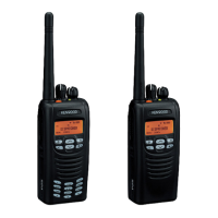
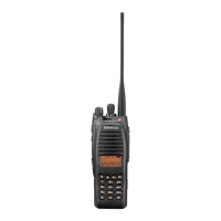
TK-5220
VHF P25 TRANSCEIVER
MIC
1
2
ABC
5
JK
L
0
8
TUV
4
7
GH
I
PQRS
3
DEF
6
MNO
MIC
#
9
WXY
Z
Knob (Selector)
(K29-9408-13)
Knob (Selector)
(K29-9408-13)
Knob (Volume)
(K29-9407-03)
Knob (Volume)
(K29-9407-03)
Helical Antenna
(KRA-22: option)
Badge
(B43-1634-04)
Badge
(B43-1634-04)
Knob (PTT)
(K29-9405-03)
Knob (PTT)
(K29-9405-03)
Plastic cabinet assy
(18 key)
(A02-4003-23)
Plastic cabinet assy
(6 key)
(A02-4002-23)
Packing (6 key)
(G53-1765-11)
Packing (18 key)
(G53-1766-11)
GENERAL ................................................................... 2
SYSTEM SET-UP ....................................................... 3
REALIGNMENT ......................................................... 4
INSTALLATION .......................................................... 6
DISASSEMBLY FOR REPAIR .................................... 7
CIRCUIT DESCRIPTION .......................................... 11
COMPONENTS DESCRIPTION ............................... 17
PARTS LIST ............................................................. 19
EXPLODED VIEW .................................................... 30
PACKING .................................................................. 31
TROUBLE SHOOTING ............................................ 32
ADJUSTMENT ........................................................ 35
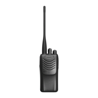
Does not come with antenna. Antenna is available
as an option.
TERMINAL FUNCTION ........................................... 56
PC BOARD
CONTROL UNIT (X53-4480-XX) ........................ 64
TX-RX UNIT (X57-7820-10) ............................... 68
INTERCONNECTION DIAGRAM ............................ 72
SCHEMATIC DIAGRAM .......................................... 74
BLOCK DIAGRAM .................................................. 88
LEVEL DIAGRAM ................................................... 92
OPTIONAL ACCESSORIES
KNB-47L (Li-ion Battery Pack) .......................... 93
KNB-48L (Li-ion Battery Pack) .......................... 93
SPECIFICATIONS ................................. BACK COVER
TK-5220 K2 TK-5220 K
CONTENTS