TK-7360/7360H/7360H
(
V
)
12
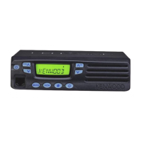
Note:
When you supply power to the TX-RX PCB after remov-
ing the TX-RX PCB from the chassis, solder the positive
and ground terminals of the DC cord (Recommendation:
E30-3448-25) to the + and GND terminals of the TX-RX
PCB.
GND
+
TX-RX PCB
Component side
6. Pull it out behind the chassis by rotating the bush
e
of
the DC cord 90 degrees in the direction of the arrow af-
ter the screw
q
in the negative terminal is removed, and
the positive terminal
w
is removed from the chassis.
DC cord
:
@
.
2. Precautions for Reassembly
1. The tab from
q
to
e
is applied the front panel fi rst. And,
r
to
y
tabs inside the front panel is pushed.
Display PCB
Speaker holder
:
@
.
=
;
B
2. When mounting the panel assembly, pass the fl at cable
through the hole of the chassis as shown below then
connect the fl at cable to connector of the panel assem-
bly.
Panel assembly
Panel
assembly
Chassis
Chassis
Hole of
the chassis
3. Fit the panel assembly into the two tabs of the chassis
top side fi rst.
Then, fit the panel assembly into the two tabs of the
chassis bottom side by turning the panel assembly.
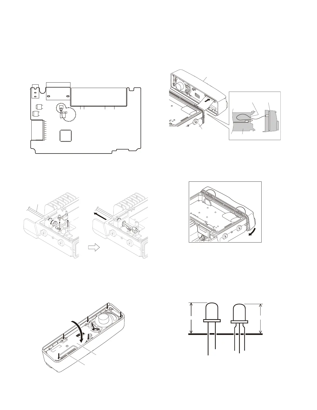
3. Correspondence when replacing the
LED (D22 and D23)
When replacing the LED (D22 and D23), it makes it to
length.
LED
LED
12mm
13mm
D22
D23
DISASSEMBLY FOR REPAIR

 Loading...