Do you have a question about the Kenwood TK-8102 and is the answer not in the manual?
| frequency range M | 450 to 490MHz |
|---|---|
| frequency range M2 | 485 to 520MHz |
| frequency range M3 | 400 to 430MHz |
| number of channels | 4 channels |
| channel spacing wide | 25kHz |
| channel spacing narrow | 12.5kHz |
| PLL channel stepping | 5, 6.25kHz |
| operating voltage | 13.6V DC ±15% |
|---|---|
| current drain standby | Less than 0.4A |
| current drain receive | Less than 1.0A |
| current drain transmit | Less than 8.0A |
| operating temperature range | –30°C to +60°C |
|---|---|
| dimensions | 160 (W) x 43 (H) x 107 (D) mm |
| weight | Approx 1.0kg |
| sensitivity 12dB SINAD wide | 0.28µV |
|---|---|
| sensitivity 12dB SINAD narrow | 0.35µV |
| selectivity wide | 75dB |
| selectivity narrow | 65dB |
| intermodulation wide | 70dB |
| intermodulation narrow | 60dB |
| spurious response | 75dB |
| audio power output | 4.0W |
| frequency stability | ±2.5ppm |
| RF power output | 25W |
|---|---|
| spurious and harmonics | 70dB |
| modulation wide | 16K0F3E |
| modulation narrow | 11K0F3E |
| FM noise wide | 45dB |
| FM noise narrow | 40dB |
| audio distortion | Less than 3% |
| frequency stability | ±2.5ppm |
Recommended safety precautions for operating and servicing the transceiver.
Steps and planning required before installing the transceiver in a vehicle or base station.
Planning for antenna systems and radio location for control stations.
Guidance on servicing the radio using manual diagrams and procedures.
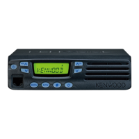
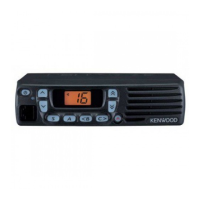
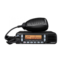
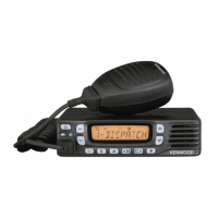
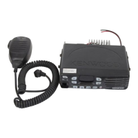
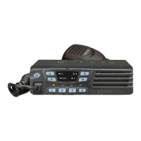
Details on front panel controls, microphone, display, and rear panel features.
Explanation of general operation and key functions like Emergency, Key Lock, Monitor, and Scan.
Guide to PC mode, programming software, interface cables, and connecting to a PC.
Instructions for data cloning between transceivers and password setup.
Details on connecting KCT-39 and KCT-18 cables for external accessories and ignition sense.
Steps for connecting the Voice Scrambler Board, including modifications and KPG-70D settings.
Detailed instructions for installing the SmarTrunk Board, including component placement and connection.
Procedures for detaching the front panel and the main transceiver cabinet.
Steps for removing the display unit PCB and mounting the front panel.
Details on receiver frequency configuration, RF amplifier, first mixer, and filtering stages.
Details on the PLL circuit's function in generating local oscillator and RF signals for reception and transmission.
Overview of the transmitter system, including power amplifier and APC circuit functions.
Explains CPU control, memory, display, and signal encoding/decoding circuits.
Details on D/A converter function and the transceiver's power supply system with protection.
List and description of components used in the display unit.
List and description of components found on the TX-RX unit.
Part numbers and descriptions for components in the display unit.
Part numbers and descriptions for components in the TX-RX unit.
Diagrams showing the physical layout and assembly of the display and TX-RX units.
Illustration and list of items included in the transceiver's packaging and how they are arranged.
Lists required test equipment and outlines procedures for transceiver alignment and tuning.
Identifies key adjustment points and provides notes on EEPROM, ICs, and fuses.
Detailed alignment steps for frequency, power, sensitivity, squelch, and deviation.
Details pin assignments and functions for the main connectors (CN1, CN2, CN3).
Component layout diagrams for the display unit's component and foil sides.
Component layout diagrams for the TX-RX unit's component and foil sides.
Detailed circuit diagrams for the TX-RX unit, covering various functional blocks.
Circuit diagrams for the display unit, showing component interconnections and functions.
A high-level overview of the transceiver's main functional blocks and their interconnections.
Illustrates signal levels at various stages of the receiver and transmitter sections.
Detailed performance metrics covering frequency, sensitivity, power, and other operational parameters.