EasyManua.ls Logo

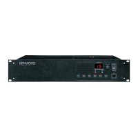
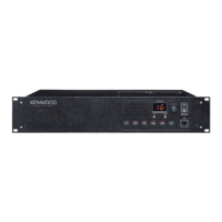
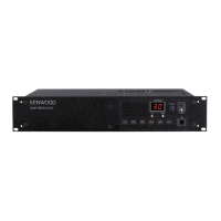
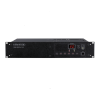
Kenwood TKR-820 User Manual

Kenwood TKR-820
90 pages
To Next Page IconTo Next Page
Page #1 background imageLoading...
Page #1 background image
SERVICE
MANUAL
©
1990-3
PRINTED
IN
JAPAN
B51-8050-00
(O)
1403
REVISED
Panel
Case
(Upper)
Dressing
plate
Knob
(TAKE
OVER,
REPEAT,
MONI)
(A20-2666-11)}
(A01-1059-01)
(A21-1519-03)
(K29-3148-04)
x
3
Knob
(POWER)
Foot
Knob
(VOL,
SQL)
Dressing
plate
Rectangular
receptacle
(MIC)
(K29-31
46-04)
(J02-0049-14)
x
4
(K29-3147-03)
x
2
(A21-1520-03)
(E08-0673-05)
CONTENTS
GENERAL
.........ccccsceececeeesseesesscecescsencerceeeuserssseceeneestes
2
RX
VCO
:
Z2
(X58-3150-XX)
wesscseccecesseecnsenssrseesene
63
SYSTEM
SET-UP
.........:sscscessscstsrnssssccuseseserenseeseers
4
TX
VCO
:
Z5
(X58-B460-XX)
....eecreeceseersseessnsscereue
64
INSTALLATION
......0..cceccsssessesssensessensccescersssseneaeeeeeses
5
MIC
AMP
:
Z7
(X59-3210-10)
....scccssececesnsereseeen
-
65
CONVERSION
.........-cccsssesceeeetsessccevensssseceusvsseneesssssees
9
IF
:
ZB
(X59-3220-1O)
...
ee
eesecesssnssteteeeeseensneesneneetan
-
66
DISASSEMBLY
FOR
REPAIR
.............::sccsseessereees
11
BPF
/
VCA
:
Z9
(X59-3230-10)
...sccsesessrsrsesssereenn
-
67
BLOCK
DIAGRAM
............--:::scssccrsercessersetseeneecsenens
17
AVR
UNIT
(X43-3040-10)
oo...
ccseeesseseesssteesseeeeeene
-
68
CIRCUIT
DESCRIPTION
.............ceccssssesssersseeessereees
19
FINAL
UNIT
(X45-3250-XX)
...cssseccceeeeessecenstseeene
-
70
SEMICONDUCTOR
DATA
..........::cecccssscssesenteseseees
26
SIGNALING
UNIT
(X52-3140-10)
.....eceesstceesseren
-72
DESCRIPTION
OF
COMPONENTS
............scsceeees
31
DISPLAY
UNIT
(X54-3070-11)
.eecscccccccssreeneessenn
~
74
PARTS
LIST
........::cccescseeceescenseeresnnseneneceesscersscasenenses
33
TX-RX
UNIT
(X57-3270-XX)
oo
ecessessssseessceesesseneenn
-
78
DISASSEMBLY
.........ccscsssscccresenensessonnseusessconeresenses
53
SIGNALING
CIRCUIT
DIAGRAM
.................00008
-
83
PACKING
..........ccssssscssesseneescsesseccceeesssseosenancansrsseneses
55
SCHEMATIC
DIAGRAM
............ccssseesececssessenernennn
-
87
ADJUSTMENT
........:ccccccscsccorccessesusenscnscunsnrsesenezetsss
56
TERMINAL
FUNCTIONG.
.............:ccceeeeecesersencoeeens
~
95
PC
BOARD
VIEWS
/
CIRCUIT
DIAGRAMS
KMC-9
(BASE
MICROPHONE)
...........--cccsecsoeeetene
-
97
RX
PLL:
Z1,
TX
PLL
:
Z4
(X58-3120-10)
....sececees
62
SPECIFICATIONS.
...........csssscsseresessees
BACK
COVER
Question and Answer IconNeed help?

Do you have a question about the Kenwood TKR-820 and is the answer not in the manual?

Kenwood TKR-820 Specifications

General IconGeneral
BrandKenwood
ModelTKR-820
CategoryRepeater
LanguageEnglish

Summary

General

Introduction

Overview of the manual's scope and purpose.

Personnel Safety

Safety precautions for personnel handling the equipment.

System Set-Up

Installation

Installing the EEPROM of Signaling Unit

Procedure for installing the EEPROM in the signaling unit.

Installing the Duplexer

Steps and products for installing the duplexer.

Attaching the Rack-mount Brackets (for EIA racks)

Instructions for attaching optional rack-mount brackets.

Conversion

Modification of the DC Switching Circuit (For Backup during a Power Failure)

Procedure for modifying the DC switching circuit for power failure backup.

Disassembly for Repair

How to Remove the Case

Steps to remove the outer case of the unit.

Disassembling the Transmitter/Receiver Section

Procedure for disassembling the transmitter/receiver section.

How to remove the TX-RX unit

Steps to remove the TX-RX unit.

Disassembling the Final ass'y unit

Procedure for disassembling the final assembly unit.

How to Remove the Panel

Steps to remove the front panel and sub-panel.

Disassembling the Sub-panel

Procedure for disassembling the sub-panel.

Disassembling the AVR unit

Steps to remove the AVR unit.

How to remove the power transformer

Steps to remove the power transformer.

Block Diagram

Circuit Description

Transmitter Circuit

Explanation of the transmitter's functional circuit blocks.

Receiver Circuit

Explanation of the receiver's functional circuit blocks.

Squelch Circuit

Detailed description of the squelch circuit operation.

RX Frequency Synthesizer

Description of the receiver frequency synthesizer circuit.

TX Frequency Synthesizer

Description of the transmitter frequency synthesizer circuit.

Microphone Amplifier

Description of the microphone amplifier circuit.

EEPROM Programming

Process of programming the EEPROM using external equipment.

Signaling Unit

Detailed explanation of the signaling unit's operations.

Accessory Connector

Functions and specifications of the accessory connector terminals.

AVR Circuit

Explanation of the Automatic Voltage Regulator (AVR) circuit.

Semiconductor Data

JLC1075DW: PL system (TXPLL, RX PLL IC2)

Technical data for the JLC1075DW IC, used in PLL systems.

M51943BML: Reset system (Signaling unit IC2), Precision reference (Display unit IC2)

Technical data for the M51943BML IC, used for reset and reference.

M5222FP: Electronic attenuator (BPF/VCA IC3)

Technical data for the M5222FP IC, an electronic attenuator.

MB504F: Prescaler (TX PLL, RX PLL IC1)

Technical data for the MB504F prescaler IC.

MB3756: Voltage regulator (TX-RX UNIT IC2)

Technical data for the MB3756 voltage regulator IC.

MC3361D: IF system (IF IC1)

Technical data for the MC3361D IC, used in the IF system.

93C46PI: EEPROM (Signaling unit IC10, Display unit IC2)

Technical data for the 93C46PI EEPROM IC.

µPC1242H: AF power amplifier (TX-RX UNIT IC1)

Technical data for the µPC1242H AF power amplifier IC.

μPD75104G-604-1B: Microprocessor (Display unit IC1)

Technical data for the μPD75104G microprocessor IC.

Description of Components

AVR UNIT (X43-3040-10)

List and description of components in the AVR unit.

DISPLAY UNIT (X54-3070-11)

List and description of components in the Display unit.

FINAL UNIT (X45-3250-XX)

List and description of components in the Final unit.

SIGNALING UNIT (X52-3140-10)

List and description of components in the Signaling unit.

TX-RX UNIT (X57-3270-XX)

List and description of components in the TX-RX unit.

Parts List

CAPACITORS

List of capacitor types, codes, and values.

RESISTORS

List of resistor types and values.

TKR-820

Parts list for the main TKR-820 unit.

AVR UNIT (X43-3040-10)

Parts list for the AVR unit.

FINAL UNIT (X45-3250-XX)

Parts list for the Final unit.

DC BACK UP

Parts list for DC Back Up modification.

AVR UNIT (X43-3040-10)

Parts list for the AVR unit.

AVR UNIT (X43-3040-10)

Parts list for the AVR unit.

FINAL UNIT (X45-3250-XX)

Parts list for the Final unit.

FINAL UNIT (X45-3250-XX)

Parts list for the Final unit.

SIGNALING UNIT (X52-3140-10)

Parts list for the Signaling unit.

SIGNALING UNIT (X52-3140-10)

Parts list for the Signaling unit.

DISPLAY UNIT (X54-3070-11)

Parts list for the Display unit.

DISPLAY UNIT (X54-3070-11)

Parts list for the Display unit.

DISPLAY UNIT (X54-3070-11)

Parts list for the Display unit.

DISPLAY UNIT (X54-3070-11)

Parts list for the Display unit.

TX-RX UNIT (X57-3270-XX)

Parts list for the TX-RX unit.

TX-RX UNIT (X57-3270-XX)

Parts list for the TX-RX unit.

TX-RX UNIT (X57-3270-XX)

Parts list for the TX-RX unit.

TX-RX UNIT (X57-3270-XX)

Parts list for the TX-RX unit.

TX-RX UNIT (X57-3270-XX)

Parts list for the TX-RX unit.

RX VCO: Z2 (X58-3150-XX)

Parts list for the RX VCO.

TX VCO: Z5 (X58-3460-XX)

Parts list for the TX VCO.

MIC AMP: Z7 (X59-3210-10)

Parts list for the MIC AMP.

IF: Z8 (X59-3220-10)

Parts list for the IF unit.

BPF/VCA: Z9 (X59-3230-10)

Parts list for the BPF/VCA unit.

Disassembly

Packing

Adjustment

1. Setting

Initial AC voltage and DC output connection settings.

2. Test equipment set-up

Setup instructions for test equipment.

3. Voltage setting

Procedure for setting voltage under different load conditions.

4. Protection

Checks for protection circuit operation.

5. Setting

Setting procedure involving frequency writing and cable connection.

6. RX PLL Lock Voltage

Adjustment of RX PLL lock voltage.

7. TX PLL Lock Voltage

Adjustment of TX PLL lock voltage.

8. TCXO

Adjustment of the TCXO frequency.

9. Power ADJ. (APC)

Adjustment of transmitter power output (APC).

10. Transmit Freq' ADJ.

Adjustment of transmitter frequency.

11. Tone deviation ADJ.

Adjustment of tone deviation with filter settings.

12. Maximum deviation ADJ.

Adjustment of maximum audio deviation.

13. MIC sensitivity ADJ.

Adjustment of microphone sensitivity.

14. DQT waveform correction

Correction of DQT waveform.

15. RX sensitivity ADJ.

Adjustment of receiver sensitivity.

16. Squelch

Adjustment of squelch level and sensitivity.

17. Preset squelch ADJ.

Adjustment of preset squelch level.

18. Hangup timer ADJ.

Adjustment of the hangup timer.

19. T.O.T

Adjustment of the Time-Out Timer.

20. Repeater TX deviation

Adjustment of repeater transmitter deviation.

21. Signaling squelch

Adjustment of signaling squelch sensitivity.

22. TAKE-OVER

Check of the TAKEOVER LED status.

PC Board Views / Circuit Diagrams

RX PLL: Z1, TX PLL : Z4 (X58-3120-10)

Component and foil side views of RX/TX PLL circuits.

RX VCO: Z2 (X58-3150-XX)

Component and foil side views of the RX VCO circuit.

TX VCO: Z5 (X58-3460-XX)

Component and foil side views of the TX VCO circuit.

MIC AMP : Z7 (X59-3210-10)

Component and foil side views of the MIC AMP circuit.

IF: Z8 (X59-3220-10)

Component and foil side views of the IF unit circuit.

BPF/VCA: Z9 (X59-3230-10)

Component and foil side views of the BPF/VCA circuit.

AVR UNIT (X43-3040-10)

Component and foil side views of the AVR unit.

FINAL UNIT (X45-3250-10)

Component and foil side views of the Final unit.

SIGNALING UNIT (X52-3140-10)

Component and foil side views of the Signaling unit.

DISPLAY UNIT (X54-3070-11)

Component side view of the Display unit.

TX-RX UNIT (X57-3270-XX)

Component and foil side views of the TX-RX unit.

KMC-9 (Base Microphone)

External View

External visual representation of the KMC-9 microphone.

Chassis Removal

Steps for removing the microphone chassis.

Removal of Microphone Element and Microphone Amplification Unit

Steps to remove the microphone element and amplification unit.

Switch Unit Removal

Procedure for removing the switch unit.

Removing Microphone Plug

Method for removing the microphone plug.

Parts List

List of parts for the KMC-9 microphone.

Specifications

General

General operating parameters like frequency range and power.

Receiver

Receiver performance specifications.

Transmitter

Transmitter performance specifications.

Signaling

Specifications for signaling functions like QT and DQT.

Related product manuals