EasyManua.ls Logo

Kenwood TKR-D810 Service Manual

Kenwood TKR-D810
3 pages
To Next Page IconTo Next Page
Page #1 background imageLoading...
Page #1 background image
JVC KENWOOD Corporation
SERVICE MANUAL
This product uses Lead Free solder.
This product complies with the
RoHS
directive for the European market.
© 2014-7 PRINTED IN JA PAN
RQ034
(
K
)
B5B-7144-00
TKR-D810
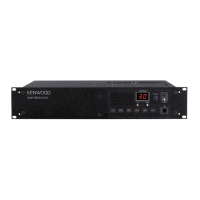
UHF DIGITAL BASE-REPEATER
N SYNC
REFIN RXIN
TX OUT
CONTROL
I/O
TEST/SPKR
DC 13.2V
FUSE 15A
CH/STATUS
VOLUME
BUSY
TX
POWER
MIC
Panel assy
(A6C-0002-00)
Knob (Power)
(K29-9106-04)
Key top
(K29-9370-02)
Knob (Volume)
(K29-5389-03)
Modular jack
(E58-0522-05)
Rear panel
(A82-0077-02)
Antenna cable (REF IN)
(E30-7690-05)
Antenna cable (RX IN)
(E30-3418-15)
Lead wire with connector
(ACC15P)
(E37-0913-05)
Lead wire with connector
(DSUB25P)
(E37-1376-05)
Modular jack x 2
(E58-0533-05)
DC cord (Ext DC in)
(E30-3414-05)
Blade fuse (15A/32V)
(F05-1537-05)
Antenna cable (TX OUT)
(E30-7528-15)
GENERAL ................................................................... 2
SYSTEM SET-UP ........................................................ 3
REALIGNMENT ......................................................... 3
OPERATING FEATURES ............................................ 5
INSTALLATION .......................................................... 6
MODIFICATION ......................................................... 8
DISASSEMBLY FOR REPAIR ..................................... 9
CIRCUIT DESCRIPTION .......................................... 10
COMPONENTS DESCRIPTION ............................... 19
PARTS LIST .............................................................. 21
EXPLODED VIEW ..................................................... 44
PACKING .................................................................. 46
TROUBLE SHOOTING ............................................. 47
ADJUSTMENT......................................................... 52
TERMINAL FUNCTION ........................................... 64
PC BOARD
FINAL UNIT (X45-4022-71) ................................. 72
CONTROL UNIT (X53-4580-10) ........................... 76
DISPLAY UNIT (X54-4060-20) ............................. 80
TX-RX UNIT (X57-8972-72) ................................. 84
RX VCO/PLL UNIT (X58-5210-10) ....................... 88
TX VCO/PLL UNIT (X58-5220-10) ....................... 89
INTERCONNECTION DIAGRAM ............................ 90
SCHEMATIC DIAGRAM .......................................... 92
BLOCK DIAGRAM ................................................. 104
OPTIONAL ACCESSORIES
KES-5 (EXTERNAL SPEAKER) .......................... 107
SPECIFICATIONS .................................. BACK COVER
APPENDIX (SCHEMATIC DIAGRAM X53-458)
CONTENTS

Other manuals for Kenwood TKR-D810

Question and Answer IconNeed help?

Do you have a question about the Kenwood TKR-D810 and is the answer not in the manual?

Kenwood TKR-D810 Specifications

General IconGeneral
CertificationFCC, IC
Built-in displayYes
Operating temperature (T-T)-30 - 60 °C
Channels quantity30 channels
Reception range (UHF)450 - 520 MHz
Number of programmable buttons6
Input voltage13.6 V
Power consumption (max)40 W
Weight and Dimensions IconWeight and Dimensions
Depth340 mm
Width483 mm
Height88 mm
Weight9700 g

Summary

General Information and Safety

Introduction and Manual Scope

Overview of the manual's purpose, intended audience, and coverage of service bulletins or revisions.

Ordering Replacement Parts

Procedure for identifying and ordering correct replacement parts using part numbers and chassis/kit information.

Personal Safety Precautions

Recommended safety measures during operation and servicing, including antenna proximity, RF connectors, and grounding.

Service Guidance

Information on servicing the transceiver, referencing schematic diagrams, PCB views, and alignment procedures.

System Set-up

Repeater Programming and Setup

Overview of the system setup process, including required hardware and software for programming.

Installation in Optional Space

Information regarding installation in an optional space, potentially related to external components or mounting.

External Speaker Installation

Details on installing an external speaker, specifically mentioning the KES-5 installation.

Realignment Procedures

Modes of Operation

Description of different operational modes: User, PC, PC programming, PC test, and firmware programming.

Entering Operational Modes

Instructions on how to enter specific modes like User mode, PC mode, and Firmware programming mode.

PC Mode Configuration

Details on using PC mode for programming, including connection procedures and entering PC mode.

Related product manuals