TM-V71A/V71E
3
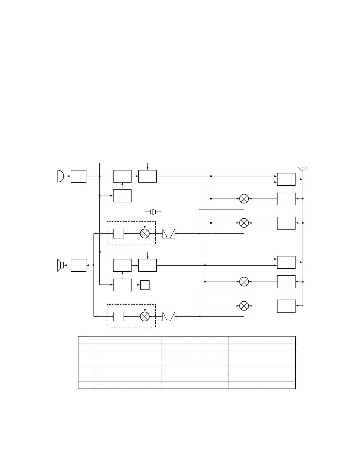
1. Frequency Confi guration
The TM-V71A/V71E has an individual VCO and PLL unit
for both band A and band B. Using these separate VCO and
PLL circuits, it can receive 2 separate bands at the same
time. You can also perform full-duplex operation.
The band A VCO is used for the following functions:
(i) VHF/UHF transmission
(ii) The first local oscillator for the band A (VHF)
reception.
(iii) The first local oscillator for the band A (UHF)
reception.
The band B VCO is used for the following functions:
(i) VHF/UHF transmission
(ii) The first local oscillator for the band B (VHF)
reception.
(iii) The first local oscillator for the band B (UHF)
reception.
The PLL reference frequency is generated by a 12.8MHz
(band A) and a 16.8MHz (band B) crystal oscillator connected
to the band A and band B PLL ICs. This reference frequency
is used for both PLL circuits. The 45.505MHz second local
oscillator for band A is generated by the FM IC crystal
oscillator circuit. The second local oscillator for the band B
uses the tripled 16.8MHz reference oscillator frequency.
Note:
The PCB layout and the mounting parts are the same for the
band A VCO (X57-731 B/6) and band B VCO (X57-731 C/6),
although the PCB silk print is different.
AF
AMP
TCXO
16.8MHz
PLL B
MIC
AMP
VCO B
MCF
49.95MHz
2dn IF
450kHz
DET
x3
FM IC
50.4MHz
TCXO
12.8MHz
Band A
VHF RX
VHF TX
PLL A VCO A
MCF
45.05MHz
2dn IF
455kHz
DET
FM IC
45.505MHz
1st IF
45.05MHz
1st IF
49.95MHz
C
A
A
Band A
UHF RX
D
B
B
Band B
VHF RX
UHF TX
E
A
Band B
UHF RX
F
B
MIC
SP
ANT
Fig. 1 Frequency confi guration
K type E type M4 type
A 144.000 ~147.995MHz 144.000~145.995MHz 144.000~145.995MHz
B 438.000~449.995MHz 430.000~439.995MHz 430.000~439.995MHz
C 189.050~193.045MHz 189.050~191.045MHz 189.050~191.045MHz
D 392.950~404.945MHz 384.950~394.945MHz 384.950~394.945MHz
E 193.950~197.945MHz 193.950~195.945MHz 193.950~195.945MHz
F 388.050~400.045MHz 380.050~390.045MHz 380.050~390.045MHz
CIRCUIT DESCRIPTION

 Loading...