EasyManua.ls Logo

Kenwood TR-751A - SSB Squelch Circuit

Kenwood TR-751A
83 pages
Print Icon
To Next Page IconTo Next Page
To Previous Page IconTo Previous Page
Loading...
TR-751A/E
CIRCUIT
DESCRIPTION
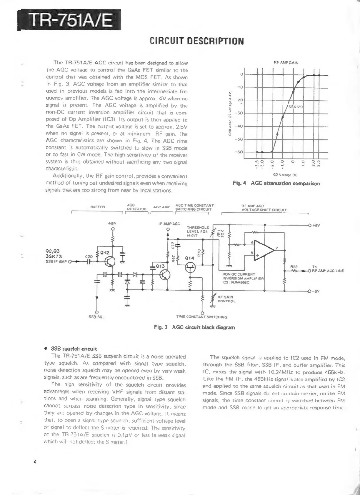
The
TR-751A/E
AGC
circuit
has
been
designed
to
allow
the
AGC
voltage
to
control
the
GaAs
FET
similar
to
the
control
that
was
obtained
with
the
MOS
FET.
As
shown
in
Fig.
3,
AGC
voltage
from
an
amplifier
similar
to
that
used
in
previous
models
is
fed
into
the
intermediate
fre-
quency
amplifier.
The
AGC
voltage
is
approx.
4V
when
no
signal
is
present.
The
AGC
voltage
is
amplified
by
the
non-DC
current
inversion
amplifier
circuit
that
is
com-
posed
of
Op
Amplifier
(1C3).
Its
output
is
then
applied
to
the
GaAs
FET.
The
output
voltage
is
set
to
approx.
2.5V
when
no
signal
is
present,
or
at
minimum
RF
gain.
The
AGC
characteristics
are
shown
in
Fig.
4.
The
AGC
time
constant
is
automatically
switched
to
slow
in
SSB
mode
or
to
fast
in
CW
mode.
The
high
sensitivity
of
the
receiver
system
is
thus
obtained
without
sacrificing
any
two
signal
characteristic.
Additionally,
the
RF
gain
control,
provides
a
convenient
method
of
tuning
out
undesired
signals
even
when
receiving
signals
that
are
too
strong
from
near
by
local
stations.
AGC
BUFFER
OErELTOR
VF
AGC
TIME
CONSTANT
AGC AMP
SWITCHING
CIRCUIT
RF
AMP
GAIN
wav.
0d8
when
G2
volta
G2
Voltage
(v)
Fig.
4
AGC
attenuation
comparison
RF
AMP
AGC
VOLTAGE
SHIFT
CIRCUIT
VF VF
IF
AMP
AGC
1 r
71
0
+8V
THRESHOLO.
LEVEL
AO.
3
2,03
3SK73
c20
SSB
IF
AMP
O—=—|
|
To
O
RF
AMP AGC
LINE
NON-DC
CURRENT
INVERSION
AM
1C3
:
NIMASSBC
g
RF
GAIN
CONTROL
fo)
Sse
SOL
TIME
CONSTANT
SWITCHING
Fig.
3
AGC
circuit
black
diagram
©@
SSB
squelch
circuit
The
TR-751A/E
SSB
suqlech
circuit
is
a
noise
operated
type
squelch.
As
compared
with
signal
type
squelch,
noise
detection
squelch
may
be
opened
even
by
very
weak
signals,
such
as
are
frequently
encountered
in
SSB.
The
high
sensitivity
of
the
squelch
circuit
provides
advantages
when
receiving
VHF
signals
from
distant
sta-
tions
and
when
scanning.
Generally,
signal
type
squelch
cannot
surpass
noise
detection
type
in
sensitivity,
since
they
are
opened
by
changes
in
the
AGC
voltage.
It
means
that,
to
open
a
signal
type
squelch,
sufficient
voltage
level
of
signal
to
deflect
the
$
meter
is
required.
The
sensitivity
of
the
TR-751A/E
squelch
is
0.14V
or
less
(a
weak
signal
which
will
not
deflect
the
S
meter.)
The
squelch
signal
is
applied
to
1C2
used
in
FM
mode,
through
the
SSB
filter,
SSB
IF,
and
buffer
amplifier.
This
IC,
mixes
the
signal
with
10.24MHz
to
produce
455kHz.
Like
the
FM
IF,
the
455kHz
signal
is
also
amplified
by
1C2
and
applied
to
the
same
squelch
circuit
as
that
used
in
FM
mode.
Since
SSB
signals
do
not
contain
carrier,
unlike
FM
signals,
the
time
constant
circuit
is
switched
between
FM
mode
and
SSB
mode
to
get
an
appropriate
response
time.