EasyManua.ls Logo

Kenwood TR-751A - RECEIVER SYSTEM; Front End and AGC Circuit

Kenwood TR-751A
83 pages
Print Icon
To Next Page IconTo Next Page
To Previous Page IconTo Previous Page
Loading...
RECEIVER
SYSTEM
©
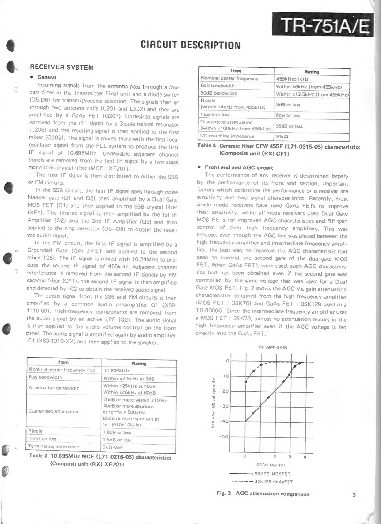
General
Incoming
signals
from
the
antenna
pass
through
a
low-
Pass
filter
in
the
Transmitter
Final
unit
and
a
diode
switch
(D5,D6)
for
transmit/receive
selection.
The
signals
then
go
through
two
antenna
coils
(L201
and
L202)
and
then
are
amplified
by
a
GaAs
FET
(Q201).
Undesired
signals
are
removed
from
the
RF
signal
by
a
3-pole
helical
resonator
(L203)
and
the
resulting
signal
is
then
applied
to
the
first
mixer
(Q202).
The
signal
is
mixed
there
with
the
first
local
oscillator
signal
from
the
PLL
system
to
produce
the
first
IF
signal
of
10.695MHz.
Undesiable
adjacent
channel
signals
are
removed
from
the
first
IF
signal
by
a
two
stage
monolithic
crystal
filter
(MCF
:
XF201).
The
first
IF
signal
is
then
distributed
to
either
the
SSB
2
@
or
FM
circuits.
@
In
the
SSB
circuit,
the
first
IF
signal
goes
through
noise
blanker
gate
(D1
and
D2)
then
amplified
by
a
Dual
Gate
MOS
FET
(Q1)
and
then
applied
to
the
SSB
crystal
filter
(XF1).
The
filtered
signal
is
then
amplified
by
the
Ist
IF
Amplifier
(Q2)
and
the
2nd
IF
Amplifier
(Q3)
and
then
applied
to
the
ring
detector
(D5—D8)
to
obtain
the
recei-
ved
audio
signal.
In
the
FM
circuit,
the
first
IF
signal
is
amplified
bya
~
Grounded
Gate
(Q4)
J-FET
and
applied
to
the
second
é€
mixer
(Q5).
The
IF
signal
is
mixed
with
10.24MHz
to
pro-
duce
the
second
IF
signal
of
455kHz.
Adjacent
channel
~
_
interference
is
removed
from
the
second
IF
signals
by
FM
ceramic
filter
(CF1),
the
second
IF
signal
is
then
amplified
and
detected
by
IC2
to
obtain
the
received
audio
signal.
The
audio
signal
from
the
SSB
and
FM
circuits
is
then
amplified
by
a
common
audio
preamplifier
Q1
(X59-
1110-00).
High-frequency
components
are
removed
from
the
audio
signal
by
an
active
LPF
(Q2).
The
audio
signal
is
then
applied
to
the
audio
volume
control
on
the
front
6
Panel.
The
audio
signal
is
amplified
again
by
audio
amplifier
1C1
(X60-1310-XX)
and
then
applied
to
the
speaker.
Item
|
Rating
Nominal
center
frequency
(fo)
|10.695MHz
Pass
bat
width
_
‘a
___|
Within
£7.5kHz
at
348
Within
*25kHz
at
4008
Within
245kHz
at
6008
Attenuation
bandwidth
40d8
or
more
spurious
|
at
fo~fo
+
SOO0kHz
|
80d8
or
more
spurious
at
_
|
fo—(9102
10kHz)
Ripple
|
1.008
or
less
[inser
ion
loss
1.5dB
or
less
Guaranteed
attenuation
70d8
or
more
within
+
1MHz
|
3k2/00F
€
=
_
[Terminating
impedance
Table
3
10.695MHz
MCF
(L71-0216-05)
characteristics
(Composit
unit
(RX)
XF201)
TR-751A/E
CIRCUIT
DESCRIPTION
Item
|
Rating
Nominal
center
frequency
_|
455kHz#
1kHz
-
6dB
bandwidth
26kHz
(from
455kHz)
50dB
bandwidth
__|
Within
£12.5kHz
(from
455kH2)|
Ripple
(within
24kHz
from
455kH2)
_
|
948
oF
less
[iosertion
loss
—
68
or
less
_
Guaranteed
attenuation
(within
#100kHz
from
455kH2)
|
9548
oF
less
|20ka
Lv
matching
impedance
Table
4
Ceramic
filter
CFW
455F
(L71-0315-05)
characteristics
(Composite
unit
(RX)
CF1)
©
Front
end
and
AGC
circuit
The
performance
of
any
receiver
is
determined
largely
by
the
performance
of
its
front
end
section.
Important
factors
which
determine
the
performance
of
a
receiver
are
sensitivity
and
two
signal
characteristics.
Recently,
most
single
mode
receivers
have
used
GaAs
FETs
to
improve
their
sensitivity,
while
all-mode
receivers
used
Dual
Gate
MOS
FETs
for
improved
AGC
characteristics
and
RF
gain
control
of
their
high
frequency
amplifiers.
This
was
because,
even
though
the
AGC
line
was
placed
between
the
high
frequency
amplifier
and
intermediate
frequency
ampli-
fier,
the
best
way
to
improve
the
AGC
characteristic
had
been
to
control
the
second
gate
of
the
dual-gate
MOS
FET.
When
GaAs
FET’s
were
used,
such
AGC
characteris-
tics
had
not
been
obtained
even
if
the
second
gate
was
controlled
by
the
same
voltage
that
was
used
for
a
Dual
Gate
MOS
FET.
Fig.
2
shows
the
AGC
Vs.
gain
attenuation
Characteristics
obtained
from
the
high
frequency
amplifier
(MOS
FET
:
3SK76)
and
GaAs
FET
:
3SK129
used
ina
TR-9000G.
Since
the
intermediate
frequency
amplifier
uses
a
MOS
FET
:
3SK73,
almost
no
attenuation
occurs
in
the
high
frequency
amplifier
even
if
the
AGC
voltage
is
fed
directly
into
the
GaAs
FET.
RF
AMP
GAIN
OdB
when
G2
voltage
is
4V
G2
Voltage
(Vv)
————-
3SK76
MOSFET
—————
35K
129
GoAsFET
Fig.
2
AGC
attenuation
comparison
3