EasyManua.ls Logo

Kenwood TR-751A - PLL Synthesizer

Kenwood TR-751A
83 pages
Print Icon
To Next Page IconTo Next Page
To Previous Page IconTo Previous Page
Loading...
PLL
SYNTHESIZER
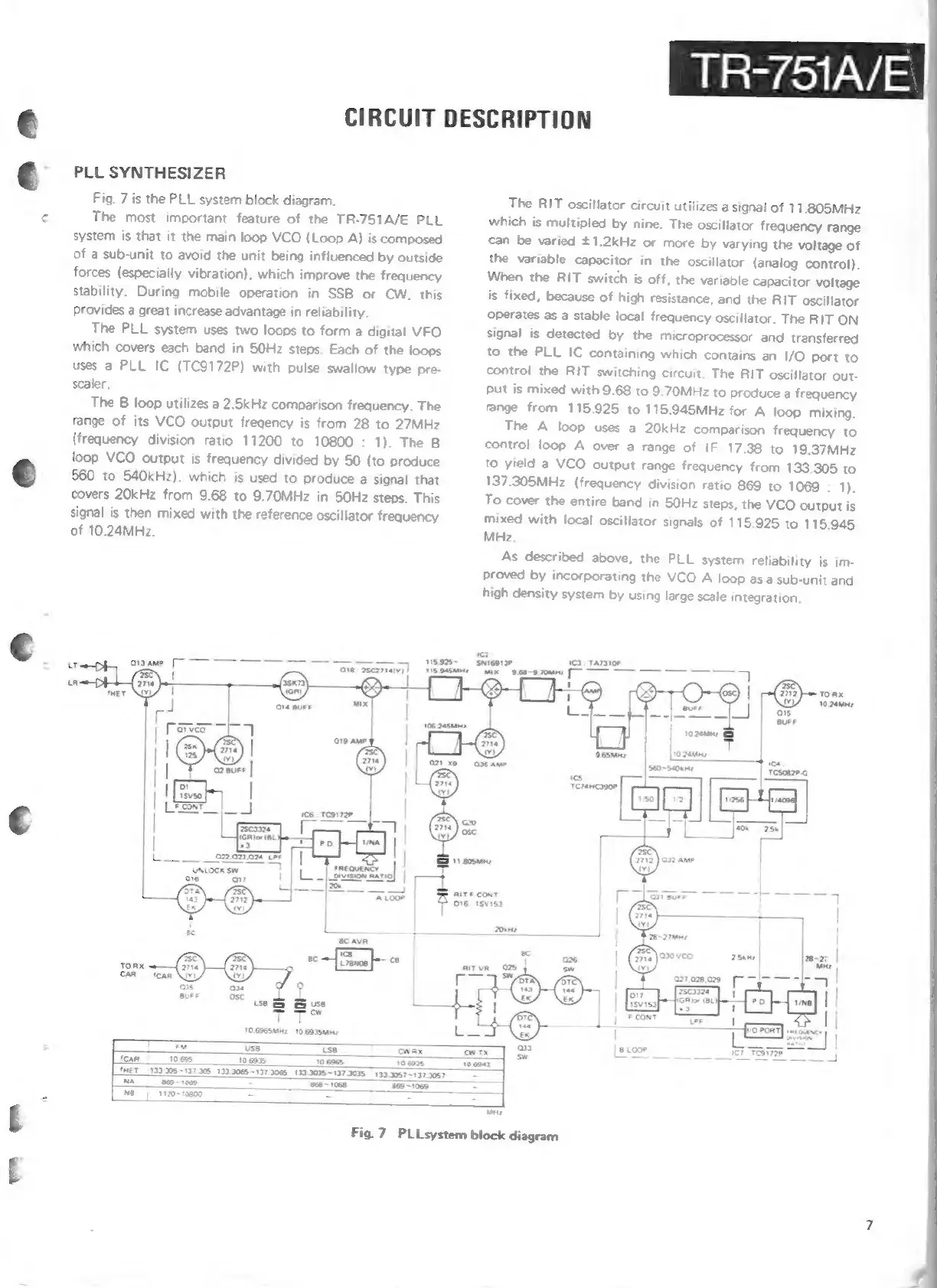
Fig.
7
is
the
PLL
system
block
diagram,
nd
The
most
important
feature
of
the
TR-751A/E
PLL
system
is
that
it
the
main
loop
VCO
(Loop
A)
is
composed
of
a
sub-unit
to
avoid
the
unit
being
influenced
by
outside
forces
(especially
vibration),
which
improve
the
frequency
stability.
During
mobile
operation
in
SSB
or
CW,
this
Provides
a
great
increase
advantage
in
reliability.
The
PLL
system
uses
two
loops
to
form
a
digital
VFO
which
covers
each
band
in
50Hz
steps.
Each
of
the
loops
uses
a
PLL
IC
(TC9172P)
with
pulse
swallow
type
pre-
scaler.
The
B
loop
utilizes
a
2.5kHz
comparison
frequency.
The
range
of
its
VCO
output
fregency
is
from
28
to
27MHz
(frequency
division
ratio
11200
to
10800
:
1).
The
B
loop
VCO
output
is
frequency
divided
by
50
(to
produce
©
560
to
540kHz).
which
is
used
to
produce
a
signal
that
covers
20kHz
from
9.68
to
9.70MHz
in
5OHz
steps.
This
signal
is
then
mixed
with
the
reference
oscillator
frequency
of
10.24MHz.
UNLOCK
Sw
6
a7
TR-751A/E
CIRCUIT
DESCRIPTION
The
RIT
oscillator
circuit
utilizes
a
signal
of
11.805MHz
which
is
multipled
by
nine.
The
oscillator
frequency
range
can
be
varied
+1.2kHz
or
more
by
varying
the
voltage
of
the
variable
capacitor
in
the
oscillator
(analog
control).
When
the
RIT
switch
is
off,
the
variable
capacitor
voltage
is
fixed,
because
of
high
resistance,
and
the
RIT
oscillator
operates
as
a
stable
local
frequency
oscillator.
The
RIT
ON
signal
is
detected
by
the
microprocessor
and
transferred
to
the
PLL
IC
containing
which
contains
an
I/O
port
to
control
the
RIT
switching
circuit.
The
RIT
oscillator
out-
Put
is
mixed
with
9.68
to
9.70MHz
to
produce
a
frequency
fange
from
115.925
to
115.945MHz
for
A
loop
mixing.
The
A
loop
uses
a
20kHz
comparison
frequency
to
control
loop
A
over
a
range
of
IF
17.38
to
19.37MHz
to
yield
a
VCO
output
range
frequency
from
133.305
to
137.305MHz
(frequency
division
ratio
869
to
1069
:
1).
To
cover
the
entire
band
in
50Hz
steps,
the
VCO
output
is
mixed
with
local
oscillator
signals
of
115.925
to
115.945
MHz.
As
described
above,
the
PLL
system
reliability
is
im-
Proved
by
incorporating
the
VCO
A
loop
asa
sub-unit
and
high
density
system
by
using
large
scale
integration.
fea
TATBIO"
raw
|
10.
20mne
5
b——4
ozenne
A
~stoune
tan
10685
fet
(133.305
~137308
139.3065
~137.3085
139.0:
NA
_
865-1088
7
NB
1120-10890
=
=
_
t
Fig.
7
PLLsystem
block
diagram