1
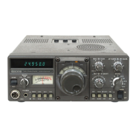
TS-130S Repair Notes
Contents
Introducon ....................................................................................................................................................... 2
Repair Process ................................................................................................................................................... 2
Preliminary Adjustments ............................................................................................................................... 2
PS-30 Power Supply Repair ............................................................................................................................ 4
AF-GEN Voltage Adjustments. ....................................................................................................................... 5
Carrier Level Adjustment ............................................................................................................................... 6
Figure 1 PS-30 Power Supply Circuit Diagram .................................................................................................. 4
Figure 2 AF-GEN PCB PSU Circuit Diagram ....................................................................................................... 5
Figure 3 Carrier PCB Circuit Diagram ............................................................................................................... 6
Figure 4 First pass of Carrier Board. Resonance at 13.03MHz ......................................................................... 7
Figure 5 T1 with 10pF Capacitor ...................................................................................................................... 7
Figure 6 T1 with 33pF Capacitor ...................................................................................................................... 8

 Loading...