Do you have a question about the Kenwood TS-130SE and is the answer not in the manual?
Describes the single-conversion system using PLL for frequency stability and reduced spurious emissions.
Features a digital display for accurate frequency indication to 100 Hz.
Allows shifting the IF crystal filter center frequency to reduce adjacent interference.
Covers all amateur bands from 3.5 to 29.7 MHz, with specific reception-only bands noted.
Provides high performance circuitry for improved signal handling and reduced blocking.
Includes a 20 dB attenuator to protect the RF amplifier and mixer from strong signals.
Enhances talk power during SSB transmission by compressing audio.
Automatically selects LSB or USB based on the band switch position.
Features a compact and lightweight design suitable for mobile and field operations.
All controls are conveniently arranged for straightforward operation.
Employs an all solid-state design for reliable and long-lasting performance.
Built-in crystal oscillator for fixed-channel operation on commonly used frequencies.
Equipped with a balanced-gate noise blanker and a 25 kHz marker.
Optional SSB narrow filter for improved selectivity.
Optional filters for CW reception offering enhanced selectivity.
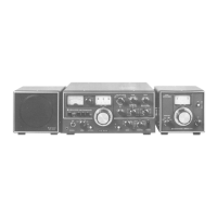
Supports a wide range of optional accessories for expanded functionality.
Details on connecting the transceiver to microphones, headphones, and other accessories.
Lists the accessories furnished with the TS-130SE transceiver.
Guidance on selecting an appropriate operating location and ensuring proper ventilation.
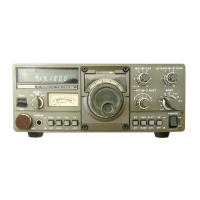
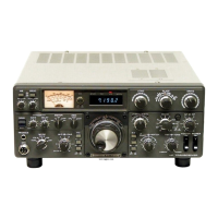
Detailed description of all controls and indicators on the front panel.
Description of connectors and controls located on the rear and top panels.
Describes the meter's functions for S-meter, IC, and ALC indication.
Explains the digital display's role in showing operating frequency accurately.
Details the function of the mode switch for SSB, LSB, USB, and CW operations.
Explains the standby switch for selecting receive or transmit modes.
Information on connecting microphones to the TS-130SE.
Details for connecting headphones, including impedance compatibility.
Describes the speech processor switch for enhancing talk power.
Explains the VOX function for automatic transmit switching via voice.
Determines the meter function during transmission (ALC or IC).
Activates the built-in fixed channel oscillator for crystal-controlled operation.
Describes the subdial for fine-tuning frequency indication.
Used to select the desired operating frequency with 1 kHz intervals.
Indicates when the RIT (Receiver Incremental Tuning) circuit is active.
Shifts the IF passband to eliminate interference from nearby signals.
Allows shifting the receive frequency by ±1.5 kHz independently of transmit.
Adjusts carrier output level, effective only during CW operation.
Adjusts microphone amplifier gain for SSB transmission.
Controls the receiver audio amplifier gain (volume).
Adjusts the receiver section's RF amplifier gain for maximum sensitivity.
Selects all amateur bands from 3.5 to 29.7 MHz.
Turns the TS-130SE transceiver ON and OFF.
Reduces pulsating ignition noises, particularly useful in mobile operation.
Inserts a 20 dB attenuator to protect against strong input signals.
Selects receive IF bandwidths between narrow and wide.
Activates the RIT circuit to allow receive frequency shifting.
Adjusts VOX circuit sensitivity for both SSB and CW operation.
Adjusts the transmit hold time of the VOX circuit.
Prevents the VOX circuit from activating due to speaker sound.
Illuminates when the internal fixed frequency oscillator controls operation.
Illuminates when the internal VFO controls transceiver operation.
UHF connector for attaching a suitable antenna.
Terminal for connecting a ground lead to prevent TVI and BCI.
Terminal for connecting a CW key.
Jack for connecting an external speaker.
Connector for interconnecting a linear amplifier or other accessories.
For connecting an external VFO-120 or DFC-230.
Connector for attaching the DC power supply.
Access for PLL reference oscillator adjustment using WWV signal.
Guidance on initial setup and receiving signals, including specific band reception.
Instructions for receiving WWV broadcasts on the 10 MHz band.
Utilizing the RF attenuator for overload protection and weak signal reception.
Activating the noise blanker to reduce pulse noise interference.
Adjusting RF gain for optimal sensitivity and S-meter indication.
Using RIT to shift receive frequency independently of transmit frequency.
Shifting the IF passband to minimize interference from adjacent signals.
Selecting narrow or wide IF bandwidth for optimal communication.
Procedures for transmitting in SSB and CW modes, including testing.
Explains the protection circuits for final transistors against high VSWR and heat.
Adjusting microphone gain for proper ALC indication during transmission.
Details on using the VOX function for automatic transmit switching.
How to activate and use the VOX switch for voice-controlled transmission.
Adjusting VOX sensitivity for optimal voice activation.
Preventing VOX activation from speaker sound.
Setting the transmit hold time for the VOX circuit.
Explains semi-break-in operation for CW using the VOX circuit.
Instructions for interconnecting and operating with a linear amplifier.
Utilizing the built-in crystal oscillator for fixed-channel communication.
Guidance for CW operation, including tuning and tone quality adjustment.
Procedure for CW tuning without optional filters.
Procedure for CW tuning with optional CW filters installed.
Steps for securely installing the TS-130SE in a vehicle.
Correct procedures for connecting and disconnecting the power cable.
Guidance on mobile antenna installation, tuning, and impedance matching.
Measures to reduce ignition and motor noise in mobile environments.
Selecting an optimal antenna location to minimize ignition noise.
Using an antenna tuner for impedance matching between antenna and transceiver.
Connecting vehicle parts with ground straps to reduce high-frequency noise.
Using specific ignition components to reduce noise generation.
Recommends direct power supply from battery terminals for optimal performance.
Considerations for vehicle power system capacity when using the transceiver.
Power requirements for fixed station operation, recommending the PS-30 supply.
Recommended antenna types and impedance matching for fixed station use.
General notes regarding factory alignment, testing, and service procedures.
Step-by-step instructions for installing optional CW and SSB filters.
Procedure for calibrating the analog dial to match the digital frequency display.
Explanation of the circuits protecting final transistors from VSWR and heat.
Information on enabling transmit capability for the new WARC bands via wiring changes.
Recommended settings for using the PC-1 Phone Patch with the TS-130SE.
Guidelines for specifying and ordering replacement parts.
Procedures for returning equipment for repair and warranty claims.
A regulated DC power supply with high capacity for the TS-130SE.
A solid-state VFO designed to match the TS-130SE for split frequency operation.
A compact digital frequency controller with 4-channel memory.
A compact antenna tuner with an illuminated SWR meter.
A cooling fan unit that allows continuous transceiver operation.
An external speaker designed to match the TS-130SE's design and tone quality.
An advanced world clock with dual display for tracking major cities.
A microphone for transceivers with touch-switch operation.
A unidirectional dynamic microphone with a locking PTT switch.
Dynamic microphones with PTT switches designed for mobile use.
Lightweight transceiver headphone with ideal tone quality.
Open-back headphones with excellent tone quality and comfortable fit.
High-performance headphones with specially designed ear pads.
Optional CW filters providing high selectivity (500 Hz and 270 Hz).
Optional SSB narrow filter for outstanding interference rejection.
| Brand | Kenwood |
|---|---|
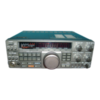
| Model | TS-130SE |
| Category | Transceiver |
| Language | English |