Do you have a question about the Kenwood TS-700G and is the answer not in the manual?
Details operating frequency ranges and supported modes for TS-700A.
Specifies output power levels for different operating modes.
Details receiver sensitivity, selectivity, and rejection performance.
Lists frequency stability, operating temperature, and power consumption.
Specifies the physical dimensions and weight of the unit.
Details operating frequency ranges and supported modes for TS-700G.
Specifies output power levels for different operating modes.
Details receiver sensitivity, selectivity, and rejection performance.
Lists frequency stability, operating temperature, and power consumption.
Specifies the physical dimensions and weight of the unit.
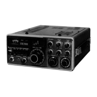
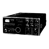
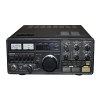
Highlights all-mode capability, dual power supply, and frequency coverage.
Details tuning mechanisms, channel capacity, and repeater operation.
Features noise blanker, squelch, and signal clarity improvements.
Describes mixer, AGC, marker circuits, and human-engineered controls.
Overview of the transceiver's circuit composition and interconnection.
Lists frequencies for various crystal oscillators.
Describes the carrier unit's function in transmit/receive.
Describes the generator unit for SSB signal generation.
Describes the FM IF unit's signal processing.
Describes the mix unit (heterodyne mixer, amplifiers).
Describes the 10-watt power amplifier unit.
Describes the BPF unit's transmit/receive coupling function.
Describes the 1 MHz marker signal circuit.
Describes the noise blanker circuit's operation.
Describes the power supply unit's operation and voltages.
Describes the VFO unit's stable oscillation circuitry.
Describes the final stage AF amplifier for speaker drive.
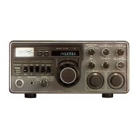
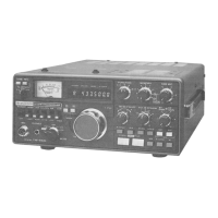
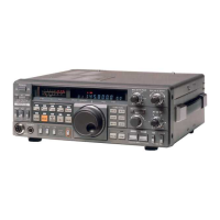
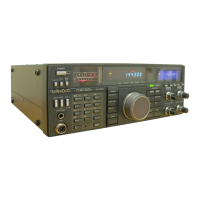
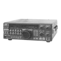
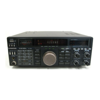
Identifies front panel controls like Power Switch and Knobs.
Identifies rear panel connectors like Mic socket and Key jack.
Identifies labels like Model Name Plate and accessories like Heat Sink.
Component layout for the Carrier unit PC board.
Component layout for the AF unit PC board.
Component layouts for VFO and Marker units.
Component layouts for Power, HET, and RX-NB units.
Component layouts for Generator, AF, and FM-IF units.
Component layouts for BPF and MIX units.
Lists capacitors and resistors with part numbers and specs.
Lists semiconductors and potentiometers with part numbers.
Lists switches, relays, coils, and quartz crystals.
Lists miscellaneous parts like sockets and fuses.
Details for packing fuses and power cords.
Details for packing accessories like microphone and speaker.
Details for packing transceiver case and foam fixtures.
Steps to separate cases and open the front panel.
Procedures for removing VFO and dial escutcheon.
Instructions for replacing power switches and the power unit.
Steps for replacing power transformer and final amplifier unit.
Troubleshooting steps for power, fuse, and signal reception problems.
Troubleshooting for noise issues and low sensitivity.
Troubleshooting for S-meter, center meter, and distorted audio.
Troubleshooting for RIT, Marker, and output level problems.
Troubleshooting for CW, SSB, FM, and general transmission output issues.
Troubleshooting RF meter deflection and distorted sound in AM.
Block diagram of signal path units.
Block diagram of core processing units.
Block diagram of amplification and power units.
Block diagram of the Power Supply Unit.
Block diagram of signal path units.
Block diagram of core processing units.
Block diagram of amplification and power units.
Block diagram of the Power Supply Unit.
Diagram showing signal levels during USB reception.
Diagram showing signal levels during CW transmission.
Level diagrams for specific units.
Procedures for adjusting CAR, VFO, and HET units.
Steps for tuning and adjusting frequencies.
Further steps for frequency tuning.
Procedure for adjusting the output signal level.
Adjustments for AM reception, noise blanker, and S-meter.
Procedures for SSB and FM reception adjustments.
Procedures for adjusting the center meter and marker unit.
Procedures for setting RIT and adjusting the main dial.
Overview of transmitting section adjustment procedures.
Procedures for adjusting the MIX unit and ALC.
Procedures for adjusting RF meter and FM transmission.
Procedures for FM transmission and TONE oscillator adjustments.
Procedures for CW/AM transmission and carrier adjustments.
Procedure for adjusting the BPF Unit.
Overview of receiver section adjustment procedures.
Procedures for AM reception and noise blanker adjustment.
Procedures for S-meter, SSB, and FM reception adjustments.
Procedures for adjusting the center meter and marker unit.
Procedures for setting RIT and adjusting the main dial.
Overview of transmitting section adjustment procedures.
Procedures for adjusting the MIX unit and ALC.
Procedures for adjusting RF meter and FM transmission.
Procedures for FM transmission and TONE oscillator adjustments.
Procedures for CW/AM transmission and carrier adjustments.
Procedure for adjusting the BPF Unit.
Procedure for adjusting the power unit.
Information on improvements to power supply and HET units.
Procedure for adjusting the HET Unit for TS-700G.
Procedure for tuning the HET unit frequency.
| Brand | Kenwood |
|---|---|
| Model | TS-700G |
| Category | Transceiver |
| Language | English |