This option has a subminiature D, 37 pin, fe-
male connector and is wired as a DCE (Data
Communications Equipment) device. It is de-
signed to be connected to a DTE (Data Ter-
minal Equipment) device. If it must be con-
nected to a DCE device, it will be necessary
to cross wires 4 and 6 as well as 22 and 24 at
one end of the connector harness.
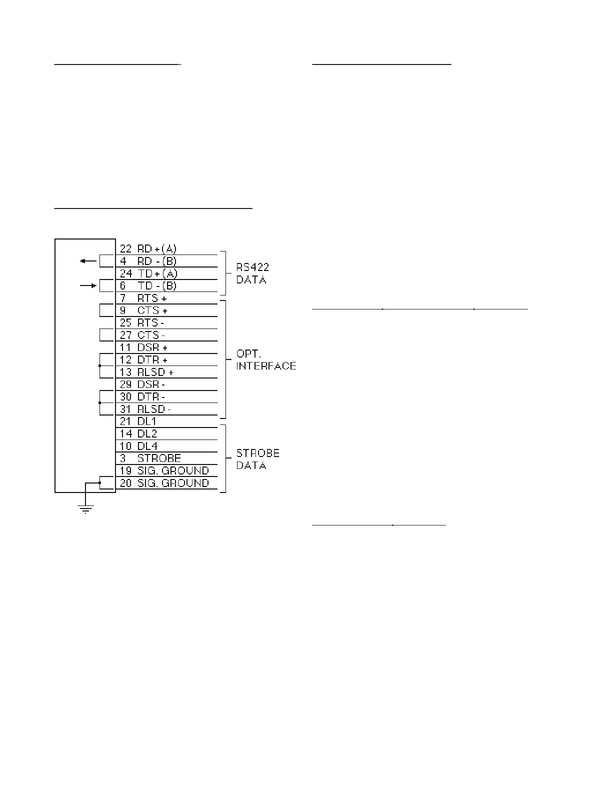
8-7.1 Wiring Diagram RS422 / Strobe
8-7.1 Wiring Diagram RS422 / Strobe
The Batcher requires only four wires for
Pin 24 (Transmit Data +A)
Other pins are jumped to simulate appropriate
responses required for some terminals.
Pins 7, 25 (Request To Send), Pins 9,
27 (Clear To Send). Jumped internally
Pins 11, 29 (Data Set Ready), Pins 13,
31 (Received Line Signal Detector),
Pins 12, 30 (Data Terminal Ready).
Jumped internally to echo back signals.
8-8 Strobe Input Electrical Requirements
8-8 Strobe Input Electrical Requirements
Both the RS232 and RS422 interface option
cards have inputs that allow data to be re-
quested over a separate strobe input and a 3
bit, data request, code input. Any number of
unit’s, data request, code lines can be linked
in parallel; as long as the source can drive
the combined load of all inputs linked together
(1.5 K Ohm divided by the total number linked
together). Data is transmitted over the serial
lines using standard RS232 or RS422 charac-
Strobe and data request inputs are pos-
itive true with signal ground as reference:
8-8.1 Strobe Input Levels
8-8.1 Strobe Input Levels
0 or low: Open or 0 to 1 VDC