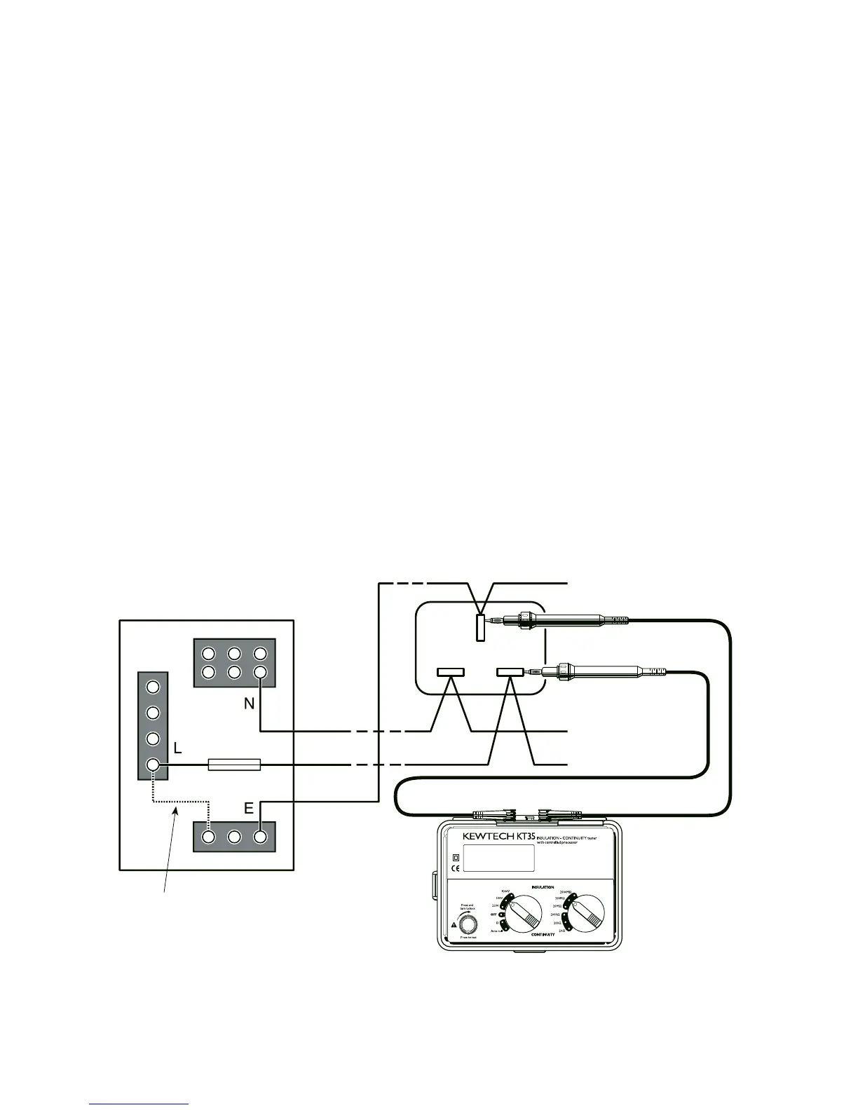
3
temporary
link
test at socket
between L and E
Typical arrangement for measuring the continuity of protective
conductors. Before proceeding with tests conductors must be
proved to be de-energised.
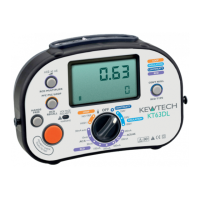
▲ 200mA continuity short circuit test current
▲ 1mA test current at the minimum load on insulation ranges
▲ Bar graph indicates test voltage-rise and decay can be
observed during insulation tests
▲ Warning of external voltage presence
▲ ‘Press to test’ button with lock down feature. Releasing the
test button automatically discharges the capacitance of a
circuit under test
▲ Auto null feature
2.2 Principles of Measurement
An Insulation/Continuity Tester performs two basic functions.
As a continuity tester the instrument can be used to measure
low values of resistance between two points in an electrical cir-
cuit. In this mode the instrument acts as a low voltage current
source. The resistance is calculated from the measurement of
the voltage and the current through the conductor. Careful