Do you have a question about the Kewtech KT63DL and is the answer not in the manual?
Features a large auto-backlit LCD for clear results in all lighting conditions.
Powers down the unit automatically after three minutes of inactivity to preserve battery life.
Position on selector switch checks battery status; low power indicated by red LED.
Powered by four AA batteries with low power consumption for extended operational life.
Allows tests to start automatically upon probe connection, freeing user's hands.
Automatically checks polarity upon live supply connection, inhibiting unsafe tests.
A rising siren indicates a potentially dangerous situation, accompanied by LED flashing.
A continuous 2-tone alarm signals unsuitable supply or incorrect polarity.
A steady beeping sound indicates a measurement is in progress or continuous testing.
A single beep signals that a measurement is complete and the result is displayed.
A short 2-tone alarm sounds when a test result indicates a likely failure.
Primary display shows test results; secondary display shows supporting information.
Interlock left exposes terminals for Continuity/Insulation tests using specific plugs.
Interlock right exposes terminals for RCD/Loop tests using different leads.
Step-by-step guide for fitting leads, selecting function, and performing continuity tests.
Feature to measure and deduct test lead resistance for accurate continuity readings.
Enables continuous continuity testing without holding buttons, activated by HANDS FREE.
Steps for fitting leads, selecting voltage, and performing insulation resistance tests.
Warns against touching energized probe tips/clips during insulation testing.
Enables continuous insulation testing without holding buttons, activated by HANDS FREE.
Fast 2-wire test for true impedance, PSC, and PFC, suitable for distribution boards.
3-wire test for Zs on RCD-protected circuits without tripping the RCD.
Displays supply voltage and calculates Prospective Fault Current (PFC/PSC).
Details required lead options for accurate loop test results.
Specifies using KAMP12 or ACC063 for No-Trip mode with 3-wire connection.
Details using ACC063 in 2-wire mode for high current loop tests.
Step-by-step guide for performing the No Trip Loop test to measure Zs.
Steps for performing high current loop test to measure Ze using specific lead configurations.
Enables hands-free operation for both No Trip and High Current loop tests.
Details test criteria for RCDs: x1/2, x1, and x5 fault currents at 0°/180°.
Allows automatic execution of all required RCD tests with a single button press.
Indicates whether the RCD has passed or failed the BS7671 test requirements.
Diagnostic feature gradually increasing fault current to identify RCD trip levels.
Tests RCD reaction times at 0° and 180° half cycles for accurate response.
Steps for selecting RCD type/rating and connecting the tester for testing.
Allows manual selection of test parameters like current multiplier and phase polarity.
Automates all 6 required tests for 30mA RCDs with one button press.
Details using ramp test to pinpoint leakage levels and diagnose nuisance tripping.
Specifications and tolerances for continuity test measurements.
Specifications and tolerances for insulation resistance test measurements.
Details output voltage levels and tolerances for insulation tests.
Specifications and tolerances for various loop test modes.
Specifications and tolerances for RCD test current and trip time accuracy.
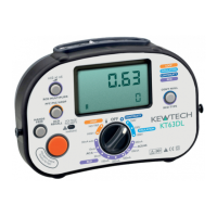
The Kewtech KT63DL is a multifunction installation tester designed for comprehensive electrical circuit analysis. It combines several critical testing functions into a single, portable device, making it suitable for both live and dead circuit testing.
The KT63DL offers a range of testing capabilities:
| Brand | Kewtech |
|---|---|
| Model | KT63DL |
| Category | Test Equipment |
| Language | English |