23
EN
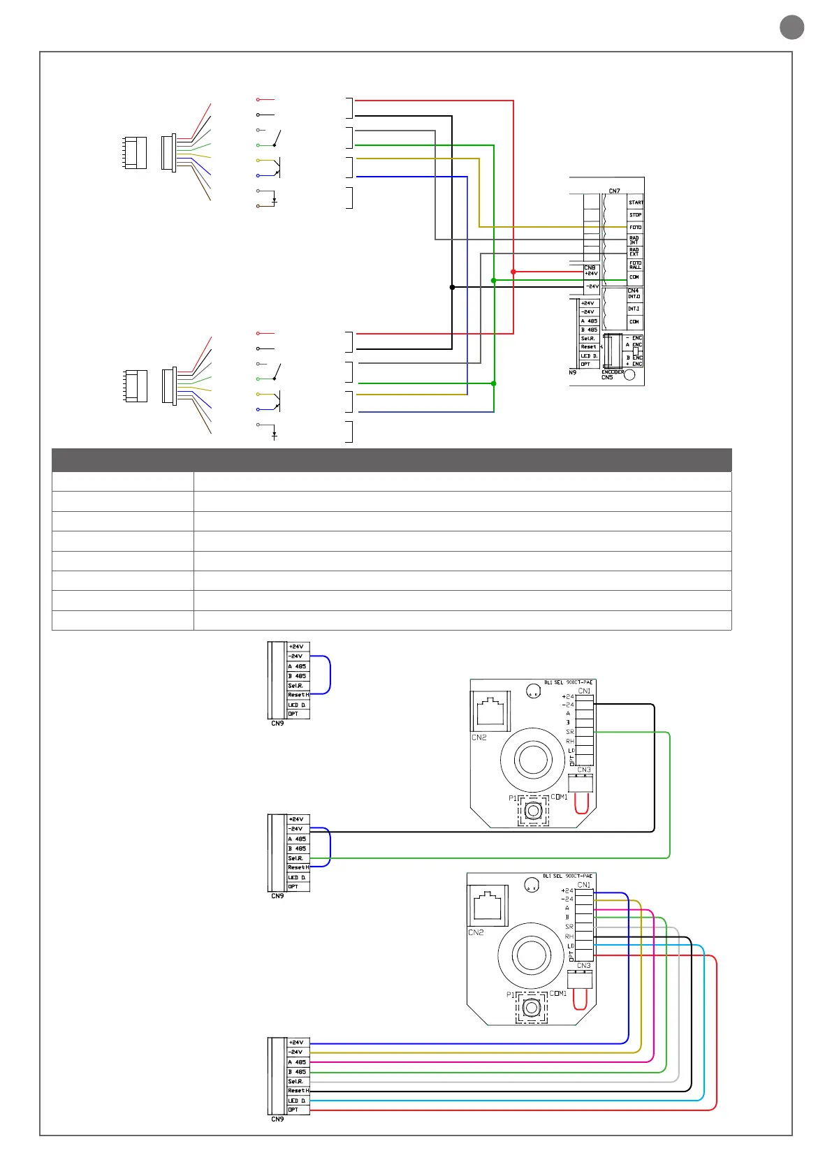
CN9 Connector for manual selector SMNPAE
+24V Positive for powering selector
-24V Negative for powering selector
A 485 Programmer connection EASY
B 485 Programmer connection EASY
Sel.R. Manual selector
Reset H. Reset
LED D. Indicator LED error
OPT Optional (not used)
1) - Without manual selector
2) - With manual selector 2 wires
3) - With complete connections 8 wires
Connections with only 2 wires: LED error indication, reset hard-
ware, EASY terminal connection.
Recommended installation.
If the manual selector is not desired, it is mandatory to set up a
bridge on the connector CN9 between the connection -24 and Reset
Sensor
connector
Sensor
connector
Cable colours
Cable colours
Descrip radar
Descrip radar
Connections
Connections
INTERNAL RADAR
CONNECTIONS DIAGRAM 900PA025CT HR100-CT
EXTERNAL RADAR
Cable
connector
Cable
connector
Red
Black
White
Green
Yellow
Blue
Grey
Brown
Red
Black
White
Green
Yellow
Blue
Grey
Brown
900PA025 CT HR100-CT
900CT-PAE
AC/DC 12 -~24V
AC/DC 12 -~24V
N.O.
COM
Collector
Transmitter
Test-P
Test-N
Input test
Exit R1,2
Exit R2,3,4,5
Power
AC/DC 12 -~24V
AC/DC 12 -~24V
N.O.
COM
Collector
Transmitter
Test-P
Test-N
Input test
Exit R1,2
Exit R2,3,4,5
Power
 Loading...


