16
EN
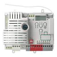
2.1 - Description of the control unit
The CT102 control unit is the most modern, efcient system for the
control of Key Automation motors for the electric opening and closure
of sliding gates and up-and-over doors.
All other, improper, use of the control unit is forbidden. The CT102 has
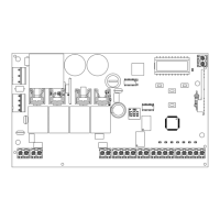
2.2 - Description of the connections
1- Motor power supply connections
2- Capacitor connector
3- 230 Vac (120 Vac) power supply connections to ashing and
courtesy lights
4- 24 Vdc power supply connection to controls and safety devices
5- RED EDGE-PH2-PH1-STOP safety warning LEDs
6- GREEN OPEN-CLOSE-PED-SBS command indicator LEDs
7- Radio PCB connector with RX4X connection (4 channels)
8- Antenna connector
9- LCD display
10- Limit switch connector
11- Limit switch indicator LED LS1
12- Limit switch indicator LED LS2
13- UP + button
14- MENU button
15- DOWN - button
16- STEPPING SBS button
17- Safety device dip switch
18- Transformer primary
19- Transformer secondary
20- F2- 500 mA rapid fuse protecting the accessories
(with CT102I 800mAT slow-acting)
21- F1- 6.3 A rapid fuse protecting the line
2.3 - Models and technical characteristics
a display allowing easy programming and constant monitoring of the
input status; the menu structure also allows easy setting of working
times and operating modes.
2 - INTRODUCING THE PRODUCT
CODE DESCRIPTION
900CT102B 230 V control unit for sliding gates or up-and-over doors
900CT102B120 120 V control unit for sliding gates or up-and-over doors
900CT102I 230 V control unit for industrial sliding gates SC202MHD. Intensive use
7
J3
RECEIVER RX4X
OUTPUT 1 = STEP BY STEP
OUTPUT 2 = PEDESTRIAN
OUTPUT 3 = OPEN
OUTPUT 4 = CLOSE
SHIELD
FUSE 2
FUSE 1
UP
MENU
SBS
DOWN
ANT
LS1
LS2
COM
PH-POW
EDGE
PH 2
EDGE
PH 1
N
L
COM Vac
CR
FLASH
+ 24 Vdc
NEG
STOP
OPEN
CLOSE
SBS
PED
COM
COM
COND
MOTOR
L1
L2
EDGE
EDGE
PH2
PH1
STOP
OPEN
PED
SBS
CLOSE
PH2
PH1
STOP
11
13
16
14
15
12
5
6
10
9
19
20
4
17
18
3
1
2
7
8
21