7
IT
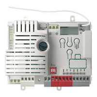
CONNETTORE SICUREZZE E COMANDI
+24 Vdc Alimentazione accessori positiva 24 Vdc, 250 mA
NEG Alimentazione accessori negativa
PH-POW
Alimentazione positiva fotocellule PH1, PH2; fototest selezionabile con parametro tph 24 Vdc, 250 mA
EDGE Costa sicurezza, ON/OFF contatto NC o resistiva 8K2 tra EDGE e EDGE (attenzione, con dip switch 1 in ON disabilita ingresso
sicurezza COSTA)
PH2 Fotocellule (apertura) contatto NC tra PH2 e COM (attenzione, con dip switch 2 in ON disabilita ingresso sicurezza FOTOCEL-
LULA 2). La fotocellula interviene in qualsiasi momento durante l’apertura dell’automazione provocando l’immediato blocco del
moto, l’automazione continuerà l’apertura al ripristino del contatto.
PH1 Fotocellule (chiusura) contatto NC tra PH1 e COM (attenzione, con dip switch 3 in ON disabilita ingresso sicurezza FOTOCEL-
LULA 1). La fotocellula interviene in qualsiasi momento durante la chiusura dell’automazione provocando l’immediato blocco
del moto invertendo il senso di marcia
STOP STOP sicurezza contatto NC tra STOP e COM (attenzione, con dip switch 4 in ON disabilita ingresso sicurezza STOP)
Tale ingresso viene considerato una sicurezza; il contatto può essere disattivato in qualsiasi momento bloccando immediatamente
l’automazione disabilitando qualsiasi funzione compresa la Chiusura Automatica
OPEN Comando APERTURA contatto NA tra OPEN e COM
Contatto per la funzione UOMO PRESENTE. Il cancello APRE nche’ e’ premuto il contatto
CLOSE Comando CHIUSURA contatto NA tra CLOSE e COM
Contatto per la funzione UOMO PRESENTE. Il cancello CHIUDE nche’ e’ premuto il contatto
PED Comando PEDONALE contatto NA tra PED e COM
Comando di apertura parziale dell’anta in base alla selezione software
SBS Comando PASSO PASSO contatto NA tra SBS e COM
Comando Apre/Stop/Chiude/Stop o in base alla selezione software
COM Comune per ingressi PH1, PH2, STOP, OPEN, CLOSE, PED, SBS
SIGNAL Antenna - segnale -
SHIELD Antenna - calza -
4.2 - Visualizzazione modalità normale
In “MODALITÀ NORMALE”, cioè quando normalmente si da alimentazione al sistema, il display LCD a 3 cifre mostra i seguenti messaggi di stato:
INDICAZIONI SIGNIFICATO
--
Cancello chiuso o riaccensione dopo spegnimento
OP
Cancello in apertura
CL
Cancello in chiusura
SO
Cancello fermato in apertura
SC
Cancello fermato in chiusura
HA
Cancello fermato da evento esterno
oP
Cancello fermato senza richiusura automatica
Pe
Cancello in posizione di apertura pedonale senza richiusura automatica
-tC
Cancello aperto con richiusura temporizzata
Tratto lampeggiante conteggio in corso
Tratto sostituito da cifra 0..9 conto alla rovescia (ultimi 10s)
-tP
Cancello aperto pedonale con richiusura temporizzata
Tratto lampeggiante conteggio in corso
Tratto sostituito da cifra 0..9 conto alla rovescia (ultimi 10s)
L--
Apprendimento avviato su necorsa (spostare il cancello dal necorsa per continuare la procedura di appren-
dimento)
LOP
Apprendimento in apertura
LCL
Apprendimento in chiusura
INDICAZIONI SIGNIFICATO
-.-
Finecorsa CHIUSUSA (un punto tra le due linee)
tC.
Finecorsa APERTURA (un punto a destra)
SO
Nessun necorsa attivato (nessun punto presente)
In aggiunta i punti tra le cifre sotto indicate mostrano lo stato dei necorsa come di seguito descritto: