6
IT
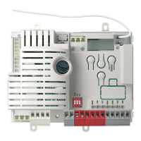
4 - INSTALLAZIONE DEL PRODOTTO
CONNETTORE MOTORE
Morsettiera collegamenti alimentazione
L1 Fase motore
COM Comune motore
L2 Fase motore
COND Condensatore motore
COLLEGAMENTO FINECORSA MOTORE
LS1 Ingresso necorsa 1
COM Comune necorsa
LS2 Ingresso necorsa 2
CONNETTORE ALIMENTAZIONI
L Fase alimentazione 230 Vac (120 Vac) 50-60 Hz
N Neutro alimentazione 230 Vac (120 Vac) 50-60 Hz
COM Vac Comune delle uscite “CR” e “FLASH”
CR Lampada di cortesia, 230 Vac (120 Vac) 100 W
FLASH Lampeggiante, 230 Vac (120 Vac) 40 W
SELETTORE DIP SWITCH
Settato su “ON” disabilita gli ingressi EDGE, PH2, PH1, STOP.
Elimina la necessita’ di ponticellare gli ingressi su morsettiera.
ATTENZIONE - con dip switch in ON le sicurezze
collegate sono escluse
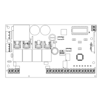
4.1 - Collegamenti elettrici
ATTENZIONE - Prima di effettuare i collegamenti vericare che la centrale non sia alimentata
OUTPUT
24 Vdc
2
3
4
1
1
2
TX
RX
NC
PH2
2
3
4
1
1
2
TX
RX
PH1
N
L
GND
_
12/24
AC/DC
GND
_
12/24
AC/DC
COM
OUT
GND
_
12/24
AC/DC
GND
_
12/24
AC/DC
COM
OUT
NC
SHIELD
FUSE 2
FUSE 1
UP
MENU
SBS
DOWN
ANT
LS1
LS2
COM
PH-POW
EDGE
PH 2
EDGE
PH 1
N
L
COM Vac
CR
FLASH
+ 24 Vdc
NEG
STOP
OPEN
CLOSE
SBS
COM
PED
COMMON
STEP BY STEP
PEDESTRIAN
CLOSE
OPEN
STOP
PHOTOCELL 1
PHOTOCELL 2
EDGE
EDGE
PHOTOTEST
NEGATIVE
COM
COND
MOTOR
L1
L2
EDGE
EDGE
PH2
PH1
STOP
OPEN
CLOSE
PED
SBS
PH2
PH1
STOP