16
EN
5 - TESTING AND COMMISSIONING THE AUTOMATION SYSTEM
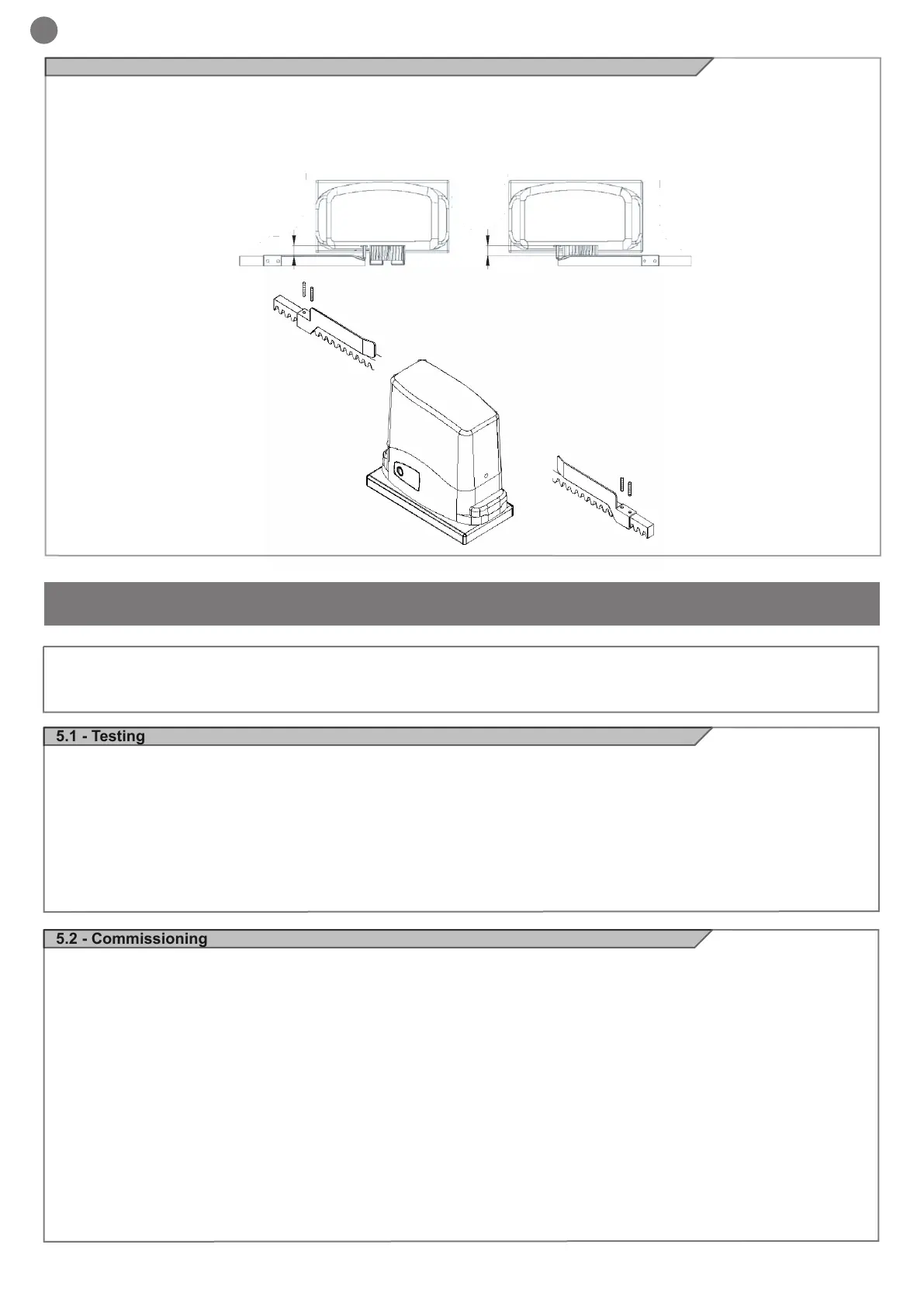
4.5 - Limit switch xing
The gate has to be equipped with stop locks at the opening and
closing, which prevent the gate derailment.
The stop lock position must assure that the limit switch brackets
don’t collide with the pinion gear.
Haul the gate manually at the opening leaving, depending on the
gate weight, a crack from 30 to 50 mm between the main gate and
mechanical stop.
Fasten the limit switch bracket through the dowels (g.11) so that
the limit switch is pressed (g.10).
Repeat the operation with the main gate at the closing.
Fig. 10
Fig. 11
5.2 - Commissioning
Once all (and not just some) of the system devices have passed the
testing procedure, the system can be commissioned;
the system’s technical dossier must be produced and kept for
10 years. It must contain the electrical wiring diagram, a drawing
or photograph of the system, the analysis of the risks and the
solutions adopted to deal with them, the manufacturer’s declaration of
conformity for all connected devices, the operator’s manual for
every device and the system maintenance plan;
x a dataplate with the details of the automation, the name of
the person who commissioned it, the serial number and year of
construction and the CE marking on the gate or door;
also t a sign specifying the procedure for releasing the system by
hand;
draw up the declaration of conformity, the instructions and
precautions for use for the end user and the system maintenance
plan and consign them to the end user;
ensure that the user has fully understood how to operate the system
in automatic, manual and emergency modes;
the end user must also be informed in writing about any risks and
hazards still present;
WARNING - after detecting an obstacle, the gate or door stops
during its opening travel and automatic closure is disabled; to
restart operation, the user must press the control button or use the
transmitter.
5.1 - Testing
All system components must be tested following the procedures
described in their respective operator’s manuals;
ensure that the recommendations in Chapter 1 - Safety Warnings -
have been complied with;
check that the gate or door is able to move freely once the automation
system has been released and is well balanced, meaning that it will
remain stationery when released in any position;
check that all connected devices (photocells, sensitive edges,
emergency buttons, etc.) are operating correctly by performing gate
or door opening, closing and stop tests using the connected control
devices (transmitters, buttons or switches);
perform the impact measurements as required by the EN12445
standard, adjusting the control unit’s speed, motor force and
deceleration functions if the measurements do not give the required
results, until the correct setting is obtained.
The system must be tested by a qualied technician, who must
perform the tests required by the relevant standards in relation
to the risks present, to check that the installation complies with
the relevant regulatory requirements, especially the EN12445
standard which species the test methods for gate and door automation
systems.
 Loading...