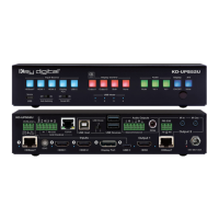
Quick Setup Guide
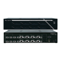
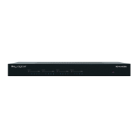
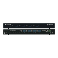
Begin with the KD-UPS52U and KD-X100MRx, KD Transmitter (sold separately), all source, display
devices, audio system, and any other connected peripherals powered off.
Connect
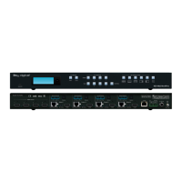
1. Connect video sources into the HDMI, Display Port, and USB-C input ports of KD-UPS52U
a. Note: For USB-C, cable must be USB-C 3.2 Gen 2 to support AV at the needed bandwidth.
b. (Optional) Connect HDMI, Display Port, USB-C, VGA sources to wall plate / table transmitter
(sold separately). Port connectivity varies by transmitter model.
2. Connect video displays/projectors to the HDMI output ports of KD-UPS52U and/or KD-X100MRX
3. Connect USB hosts and devices. For USB camera, microphone, speakers, audio DSP, keyboard, or
mouse integration, connect USB devices into desired USB A ports and USB host computer to desired
USB B ports at KD-X100MRx, KD-UPS52U, or Transmitter.
a. USB devices must be connected at same location, see USB Modes Selection Table.
b. Ensure USB toggle switches have chosen USB Device or Host as desired.
4. Connect CAT5e/6 cabling from KD-UPS52U’s HDBaseT outputs to KD-X100MRX HDBaseT input and
(optional) from KD-UPS52U’s HDBaseT input to transmitter (sold separately)
5. Connect audio to send audio of the select source into KD-Amp220 use KD-UPS52U’s analog audio de-
embed port. For other audio systems use the digital or analog outputs ports located on KD-UPS52U or
KD-X100MRx.
6. (Optional) Connect RS-232 wiring for Integrated System. If utilizing KD-AMP220 or KD-CAMUSB
integration control mode, connect RS-232 wiring from KD-UPS52U Unit Control TxD and Ground pins
into KD-AMP220 and KD-CAMUSB RxD and Ground. Using a stripped mono or stereo audio cable is
recommended, but other cables will work as well. See below diagram
7. Connect Control System. For KD-App control and/or IP control from a control system or PC, connect
TCP/IP port to network. RS-232 and IR control may also be utilized, but IP control is required for KD-
CamUSB and KD-Amp220 integrated systems.
8. (Optional) Connect display/projector’s IR/RS-232 from control system into pass-thru ports of KD-
UPS52U and IR/RS-232 ports of the KD-X100MRX.
a. Alternatively, KD-UPS52U CEC Manager features can send power on and off commands via
CEC on the HDMI connection.
9. Connect power. Screw-in power supply to the KD-UPS52U unit, and then connect power to outlets.
10. Power on sources, displays, audio systems, connected computers, USB devices and hosts to use
system.