HX3.5 Mainboard 7
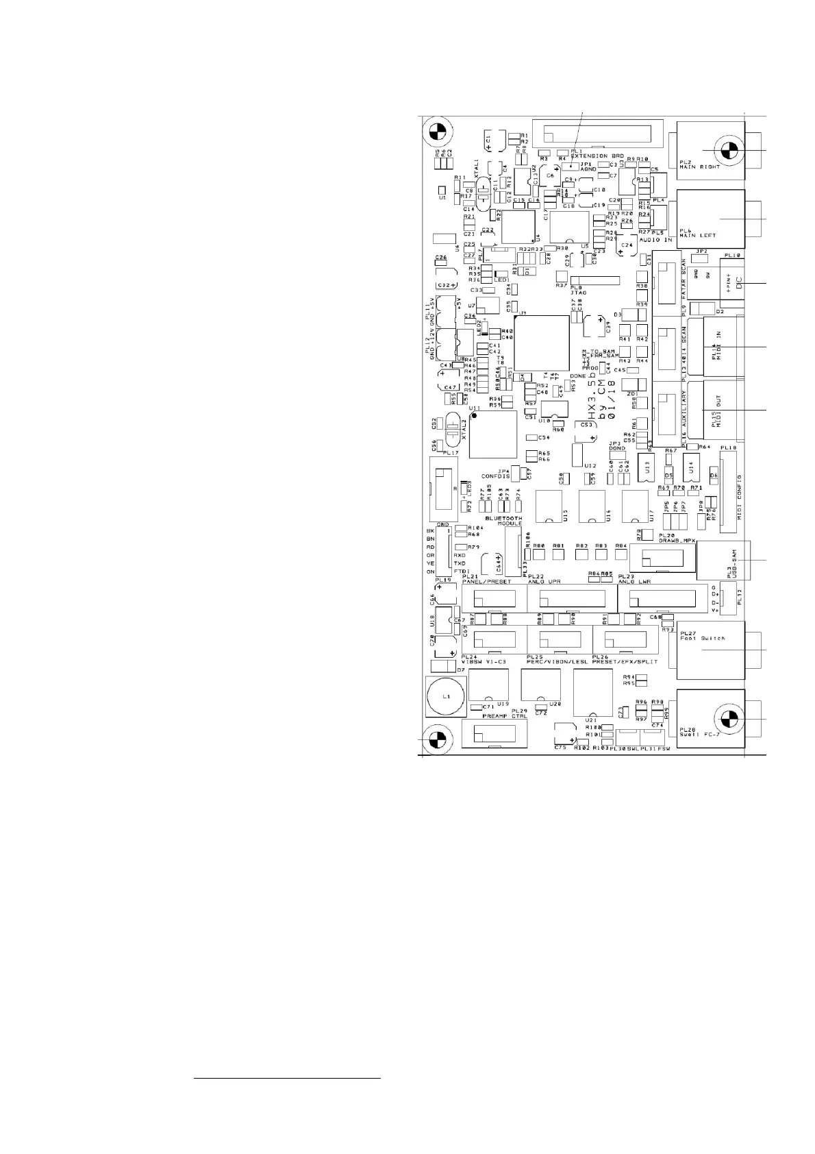
Connectors and Jumpers on the Mainboard
PL1: HX3 Extension Board (optional)
PL2: 1/4" jack Right Audio Output
PL3: USB B type socket (USB MIDI)
PL4: Stereo Audio Output; center = GND
PL5: Stereo Audio Mixer Input; center = GND
PL6: 1/4" jack Left Audio Output
PL7: DSP Debug (do not use)
PL8: FPGA Debug (do not use)
PL9: Scan Board (FatarScan2)
PL10: DC input, 5V or 9..12V/500mA, plus on center
PL11: DC input/output, 5V/500mA
PL12: DC input, 9..12V/500mA
PL13: Scan Board (Scan16, Scan61 or Bass25)
PL14: MIDI IN1
PL15: MIDI IN2/OUT
PL16: Aux digital output (do not use)
PL17: SD Card Adaptor (or ISP AVR)
PL18: MIDI IN/OUT Configuration Jumpers
PL19: Serial Interface for FTDI cable
PL20: MPX Bus (HX3 mk5 new drawbars)
PL21: MenuPanel/Preset-Boards, I2C
PL22: Analog Upper (in mk4 compatibility mode)
PL23: Analog Lower (in mk4 compatibility mode)
PL24: Vibrato Rotary Switch
PL25: Buttons/Switches Perc, Vib, Rotary control
PL26: Buttons/Switches Common Presets or Vibrato
Buttons, Reverb, Bass On Amp, Split
PL27: 1/4" jack Footswitch Rotary control
PL28: 1/4" jack Swell Pedal (FC-7 compatible)
PL29: Preamp control outputs, var. control signals
PL30: 3 pin header Swell Pedal (FC-7 compatible)
PL31: 3 pin header Footswitch Rotary control
PL32: 4pin USB header to HX3.5 Extension Board
PL33: Bluetooth/WiFi Module
JP1: Analog Ground (Probe Connection), both pins
JP2: 5V DC input on PL 10/PL12 if inserted
JP3: Digital Ground (Probe Connection), both pins
JP4: Config Disable (do not use)
JP5: Swell on Analog Input 12 (do not use)
JP6: Swell on AVR analog input PA2 (default)
JP7: Swell on AVR analog input PA7 (do not use)
JP8: Use USB for power supply (not recommended)
Default jumper setting: Insert JP6. Insert 2 jumpers on PL10 pin 2-3 and 5-6 (leftmost pin is 1) for
secondary MIDI IN.
All details about the different possible hardware configurations and a larger picture of the board
can be found in the HX3.5 Installation Manual.