60 Keysight 34921A-34925A User’s Guide
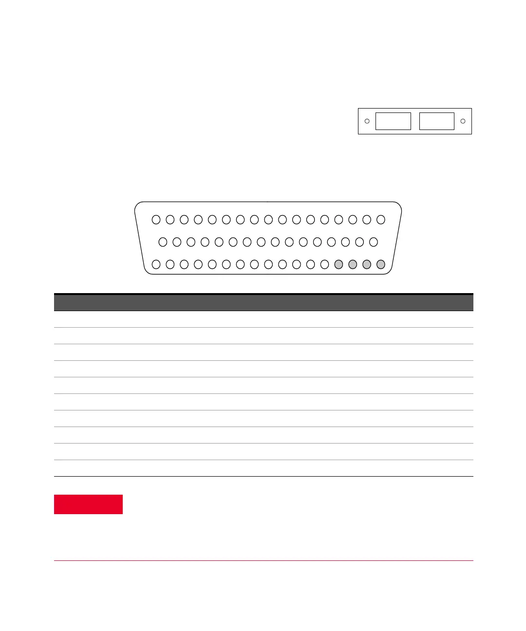
34925A D-Sub Connectors for One-Wired Mode
Bank 1
For orientation, the D-sub connector
end of the module is facing you.
Bank 1
Bank 2
34
34
35
36 37
38
39 40
41
42
43 44 45
46
47 48 49
50
18
19 20
21 22
23
24
25 26
27 28
29 30 31 32
33
GND 11 12 31 32 23 24 15 16 35 36 19 20
NC NC NC NC
Reserved 21 22 13 14 33 25 26 17 18 37 38 29 30 Interlock 1
1 2 3 4 5 6 7 8 9 1011121314151617
Interlock1123456
COM
1H
COM
1L
7 8 27 28 9 10 39 40
50-Pin D-Sub
Male Connector
Description Pin Description Pin Description Pin Description Pin Description Pin
1 1 11 35 21 19 31 37 COM1 H 7
2 2 12 36 22 20 32 38 COM1 L 8
3 3 13 21 23 39 33 23 Interlock 1 17
4 4 14 22 24 40 34 24 Interlock 1 33
5 5 15 41 25 25 35 43 Reserved 18
6 6 16 42 26 26 36 44 GND 34
7 9 17 27 27 11 37 29 No Connect 47
8 1018 2828 1238 30No Connect48
9 1319 4529 3139 15No Connect49
10 14 20 46 30 32 40 16 No Connect 50
As a safety feature, interlock 1 pins (17 and 33) on Bank 1 must be shorted to
enable the Bank 1 Analog Bus relays to close. The optional 34925T-002 (for
1-wire) terminal block shorts these pins for you. This feature protects
inadvertent routing of high voltages from the Analog Bus to the D-sub
connector of the module.