2Operation and Features
72 E364xA User’s and Service Guide
Checking the OVP operation
To check the OVP operation, raise the output voltage to near the trip point. Then
very gradually increase the output by turning the knob until the OVP circuit trips.
This will cause the power supply output to drop to near zero, the OVP1 and OVP2
annunciator to flash, and the CC annunciator to turn on. The OVP1 (or OVP2) TRIP
message also appears on the display.
Clearing the overvoltage condition
When the OVP condition occurs, the OVP1 or OVP2 annunciator flashes. When it
was caused by an external voltage source such as a battery, disconnect it first.
Clear the overvoltage condition by adjusting the output voltage level or by
adjusting the OVP trip level.
The following steps show you how to clear the overvoltage condition and return to
the normal mode operation. In the following steps, the display will return to OVP1
(or OVP2) TRIP if you allow the display to time-out after about several seconds.
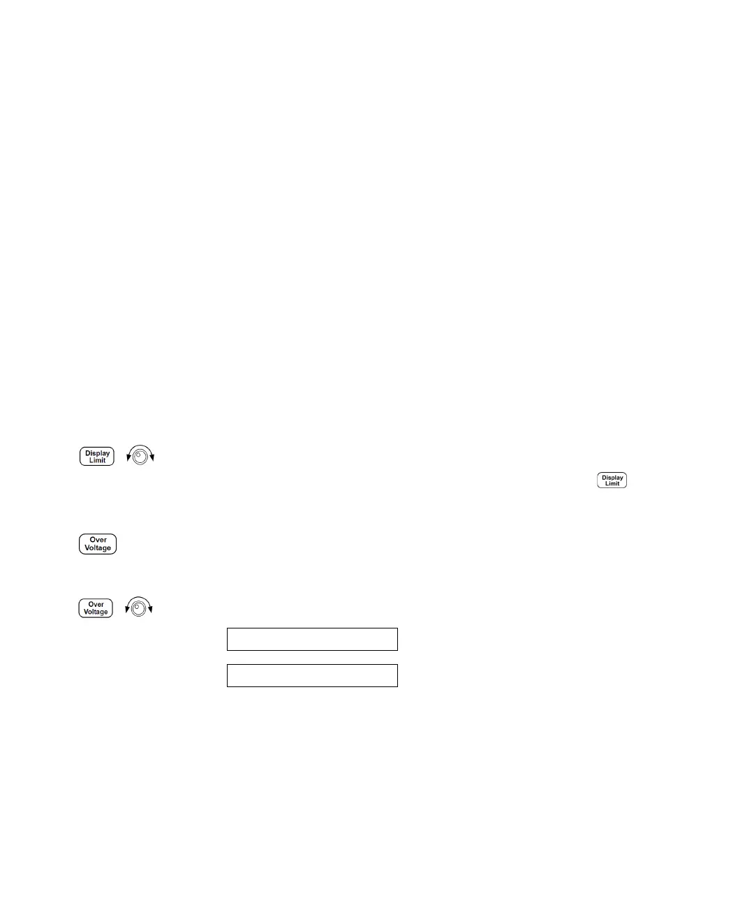
– By adjusting the output voltage level
1 Lower the output voltage level below the OVP trip point.
The OVP1 or OVP2, and Limit annunciators are flashing after is
pressed.
2 Check that you lowered the voltage level below the OVP trip point.
The OVP trip point is displayed. Do not adjust the trip point at this step.
3 Select the OVP CLEAR mode by turning the knob.
OVP ON
OVP CLEAR