20
Getting Started
STEP 4. Install the Network Analyzer Modules
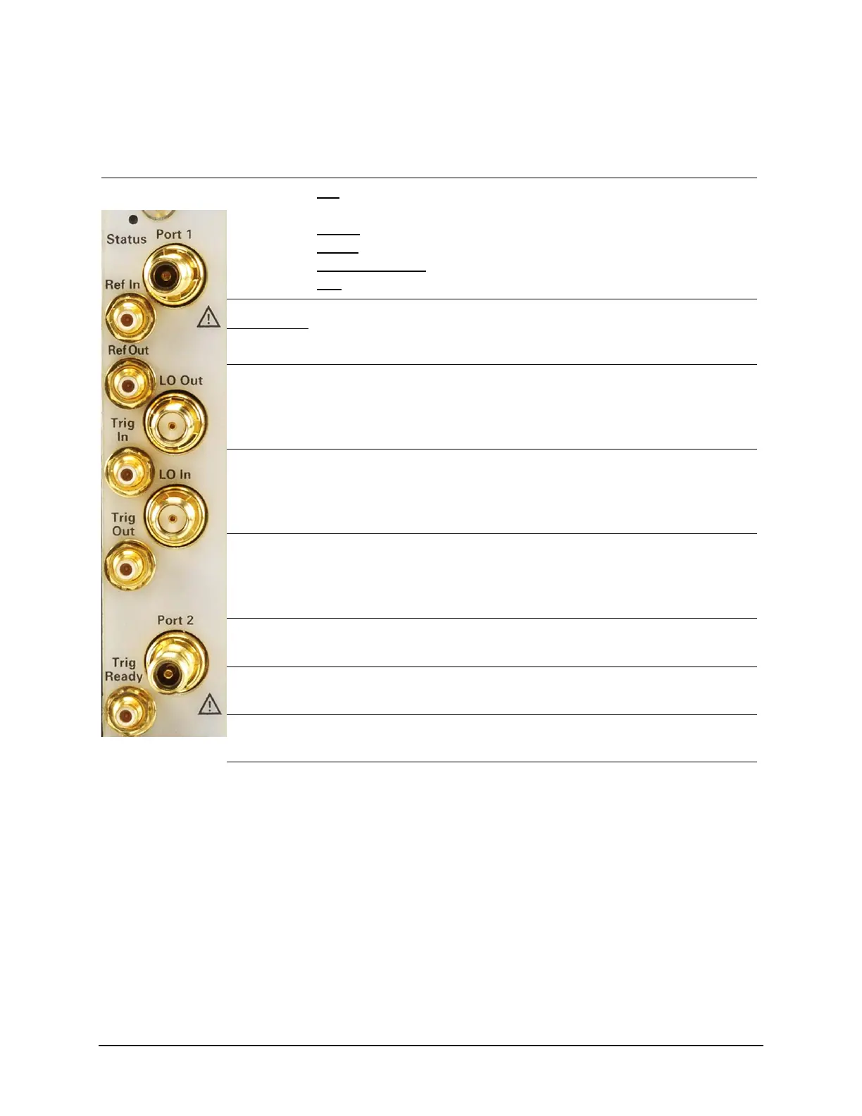
Front Panel Features
Front Panel Photo Feature Description
Status LED OFF
: Power supply off. Safe to remove the network analyzer module from
the chassis.
AMBER
: Power supply on, but no firmware is in control.
GREEN
: Firmware is in control; instrument is probably idle.
FLASHING GREEN:
A sweep or measurement has been triggered.
RED
: Last sweep had an error.
Port 1 APC 3.5 mm female connector. Sources stimulus signals for the DUT and
receives response signals from the DUT. Frequency range is determined
by the network analyzer module model.
Port 2
LO In SMA female connector. If the network analyzer module is not configured
with another module, the connector is terminated with a 50 ohm load. If
the module is configured with a module in an adjacent slot, the connector
receives the LO signal from the configured module.
LO Out SMA female connector. If the network analyzer module is not configured
with another module, the connector is terminated with a 50 ohm load. If
the analyzer module is configured with a module in an adjacent slot, the
connector provides the LO signal to the configured module.
Ref In SMB female connector. A 10 MHz external reference signal supplied to
this port can be used as the instrument frequency reference instead of the
internal frequency reference. To activate this feature on the soft front
panel, select Utility > System > Configure > External Reference.
Ref Out SMB female connector. Outputs a 10 MHz frequency reference signal for
use by other test equipment.
Trig In SMB female connector. Inputs a signal to trigger the network analyzer
module.
Trig Out SMB female connector. Outputs a signal either before or after a
measurement.
Trig Ready SMB female connector. Outputs a “READY’ signal to other devices.

 Loading...