EasyManua.ls Logo

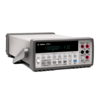
Keysight 34401A Service Manual

Keysight 34401A
165 pages
To Next Page IconTo Next Page
Page #1 background imageLoading...
Page #1 background image
Keysight 34401A
6½ Digit Multimeter
Service
Guide

Table of Contents

Other manuals for Keysight 34401A

Questions and Answers:

Keysight 34401A Specifications

General IconGeneral
Model34401A
CategoryMultimeter
ManufacturerKeysight
Display Digits6.5 digits
DC Voltage Range100 mV to 1000 V
AC Voltage Range100 mV to 750 V
Resistance Range100 Ω to 100 MΩ
Frequency Range3 Hz to 300 kHz
Frequency Accuracy±0.01% of reading
InterfaceGPIB, RS-232
Operating Temperature0 °C to 55 °C
Weight3.6 kg
Resolution100 nV
Dimensions88 mm x 213 mm x 348 mm
DC Current Range10 µA to 3 A
AC Current Range10 µA to 3 A

Summary

Specifications

DC Characteristics

Detailed accuracy specifications for DC voltage, resistance, and current measurements.

AC Characteristics

Accuracy specifications for AC voltage, current, and frequency response.

Frequency and Period Characteristics

Specifications for measuring frequency and period of signals.

General Information

Overview of power, environment, EMI, warranty, and included accessories.

Interpreting Multimeter Specifications

Explanation of key terms like digits, overrange, sensitivity, resolution, and accuracy.

Configuring for Highest Accuracy Measurements

Recommended settings for optimizing measurement accuracy.

Quick Start

To Prepare the Multimeter for Use

Steps to verify the multimeter is ready for operation and perform initial checks.

If the Multimeter Does Not Turn On

Troubleshooting guide for power-related issues, including fuse and voltage settings.

To Measure Voltage

Basic procedure for measuring DC and AC voltage using the multimeter.

To Select a Range

Explanation of autoranging and manual ranging methods for selecting measurement ranges.

To Rack Mount the Multimeter

Instructions and kits for installing the multimeter in a standard 19-inch rack cabinet.

Menu Tutorial

Front-Panel Menu Reference

Detailed listing and description of all front-panel menu options and their functions.

A Front-Panel Menu Tutorial

Step-by-step guide on navigating the multimeter's front-panel menu structure.

Calibration Procedures

Recommended Test Equipment

List of recommended test equipment for performing calibration and verification.

Performance Verification Tests

Procedures for verifying the multimeter's performance against specifications.

Zero Offset Verification

Procedure to check and verify the zero offset performance of measurement functions.

Gain Verification

Procedure to check the full-scale reading calibration for various functions and ranges.

Calibration Security Code

How to set and use a security code to prevent unauthorized calibration.

Zero Adjustment

Procedure for automatically adjusting the zero offset correction constants for all functions.

Gain Adjustment

Procedure for adjusting gain correction constants for optimal measurement accuracy.

Error Messages

List of common error messages encountered during calibration and their meanings.

Theory of Operation

Block Diagram

Overview of the multimeter's internal circuitry divided into floating and earth-referenced sections.

DC Amplifier

Explanation of the DC amplifier circuit used in most measurement functions.

AC Circuit

Explanation of the AC measurement circuit, including filters and gain stages.

A-to-D Converter

Description of the analog-to-digital conversion process using the multislope III method.

Power Supplies

Overview of the multimeter's floating and earth-referenced power supply circuits.

Service

Operating Checklist

A list of checks to perform before returning the multimeter for service or repair.

Electrostatic Discharge (ESD) Precautions

Essential guidelines to prevent ESD damage when servicing electronic components.

Troubleshooting Hints

A checklist of common failures and basic troubleshooting steps for the multimeter.

Self-Test Procedures

Information on performing internal self-tests to verify hardware functionality.

Replaceable Parts

Main PC Assembly (A1) Parts List

Detailed list of replaceable parts for the main printed circuit board assembly.

Display Assembly Replaceable Parts List

Detailed list of replaceable parts for the front-panel display assembly.

Manufacturer’s List

Contact information and codes for various component manufacturers.

Backdating

Backdating Information

Table listing changes made to the multimeter with prior serial numbers for backdating purposes.

Schematics

Mechanical Disassembly

Diagrams illustrating the procedures for disassembling the multimeter's chassis and panels.

Component Locator Diagram – Main PC Board (34401-66501)

Diagram showing the physical location of components on the main PC board.

Agilent 34401A Block Diagram

High-level block diagram illustrating the multimeter's main functional sections and interconnections.

DC Amplifier and Ohms Schematic

Schematic of the DC amplifier and the ohms current source circuitry.

AC Circuit Schematic

Schematic illustrating the AC measurement circuit, including filters and gain stages.

A/D Converter Schematic

Schematic of the analog-to-digital conversion circuitry.

Floating Logic Schematic

Schematic of the main CPU and related logic controlling instrument operation.

Earth-Referenced Logic Schematic

Schematic of the I/O processor and interface circuitry for rear panel communication.

Power Supplies Schematic

Schematic of the floating and earth-referenced power supply circuits.

Display and Keyboard Schematic

Schematic of the front panel display control and keyboard scanning circuits.

Related product manuals