Keysight E4412A and E4413A Operating and Service Guide 13
List of Figures
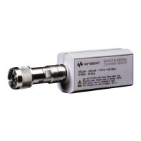
Figure 1-1 E4412A and E4413A power sensors (formerly ECP-E18A
and EXCP-E26A, respectively) . . . . . . . . . . . . . . . .18
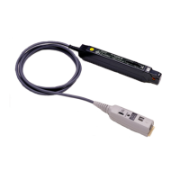
Figure 1-2 E4413A power sensor with adapter . . . . . . . . . . . . . . .23
Figure 1-3 System calibration setup . . . . . . . . . . . . . . . . . . . . . . .24
Figure 1-4 DUT measurement setup . . . . . . . . . . . . . . . . . . . . . . .26
Figure 1-5 Equipment setup for high power S11 verification . . . .28
Figure 1-6 Power linearity performance verification equipment
setup . . . . . . . . . . . . . . . . . . . . . . . . . . . . . . . . . . . .31
Figure 1-7 Zero set performance verification equipment setup . .33
Figure 1-8 Illustrated parts break down . . . . . . . . . . . . . . . . . . . .35
Figure 1-9 Removing power sensor shell . . . . . . . . . . . . . . . . . . .41