3 Operating the Power Supply Locally
46 Series N5700 User’s Guide
• Set the programming sources to the desired levels and turn the
power supply on. Adjust the programming sources to change the
power supply output.
The analog control circuits let you set the output voltage and current
limit up to 5% over the model-rated maximum value. The power supply
will operate within the extended range, however it is not recommended
to operate the power supply over its voltage and current rating, and
performance in this region is not guaranteed.
SW1 switch 3
Voltage Programming
Current Programming
Resistance Programming of Output Voltage and Current
Resistances of 0 - 5 kΩ or 0 - 10 kΩ can be selected to program the output
voltage and current limit from zero to full scale. Internal current sources
supply a 1mA current through the external resistors. The voltage drop
across the resistors is used as the programming voltage for the power
supply. To maintain the temperature stability specification of the power
supply, only use resistors that are stable and low noise, with a
temperature coefficient less than 50ppm.
Set the power supply to resistance programming as follows:
• Make sure that the power supply is turned off.
• Set SW1 setup switch 1 (for voltage) and 2 (for current) to the UP
position.
• Set SW1 setup switch 3 to select programming resistance range
according to the following table.
• Set SW1 setup switch 7 (for voltage) and 8 (for current) to the Up
position to enable resistance programming.
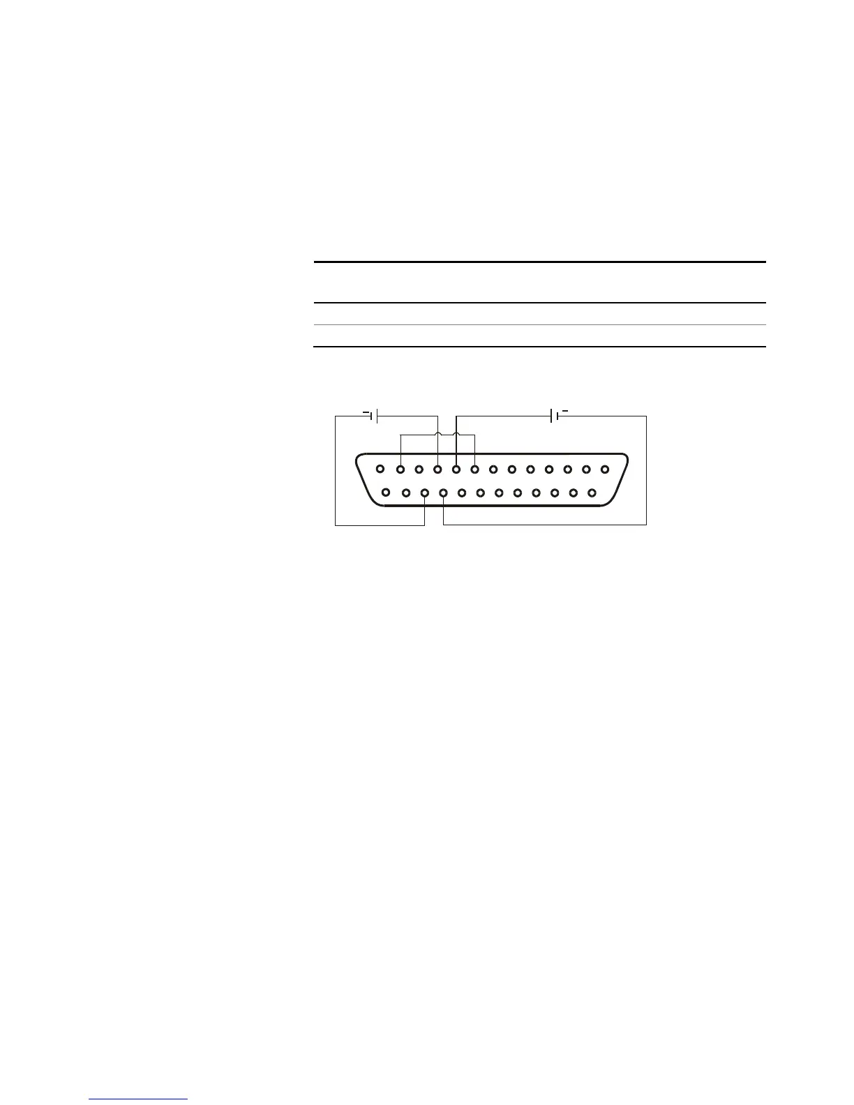
• Connect a short between J1 pin 8 and J1 pin 12 (see figure).
• Connect the programming resistors to the mating plug of J1 as
shown in the following figure. A variable resistor can control the
output over its entire range, or a combination of variable resistor
and series/parallel resistors can control the output over a
restricted portion of its range.
1
14
13
25
10
12
8
9
23
22
+
+
CURRENT LIMIT
PROGRAMMING
OUTPUT VOLTAGE
PROGRAMMING