6
OPERATION
Automatic Turn-On Selection: The KEY series offers two different automatic turn-on modes that can
be selected on the end panel; +12V and DC Offset. Using the DC Offset mode causes the REM wire to
have +12V out for turning on additional amplifi ers.
• Remote Turn-On: Set the switch to +12V to use the remote turn-on lead from your source unit. Run
18 gauge wire from the Remote Turn-On Lead on your source unit to the blue REM wire on KEY
amplifi er's wiring harness. This is the preferred automatic turn-on method.
• If 12V remote turn-on is not available, DC Offset turn-on can be used if speaker-level audio inputs
are being used. The DC offset mode detects a 3V DC offset on the speaker wires when the source
unit has been turned on.
Radio Detect: The RCA inputs on KICKER KEY amplifi ers are capable of receiving either Hi or Low-level
signals from your source unit. If you are using Hi-Level inputs, but your source unit cannot detect an audio
system present or refuses to play audio out of one or more speakers, you may need to set Radio Detect
to ON. This will activate a load resistor at the amplifi er’s inputs and tell the source unit there are speakers
present. Do NOT use Radio Detect if you are using a Low-Level input signal; doing so will greatly reduce the
input signal.
Input Gain Control with Gain Matching: The input gain control is not a volume control. It matches the
output of the source unit to the input level of the amplifi er and features Gain Matching to prevent clipping the
input. For a quick setup, turn the source unit up to about 3/4 volume (if the source unit goes to 30, turn it to
25). KICKER recommends using the test tones at www.KICKER.com/support/ to reach the most accurate
and best performing settings. Next, with gain knobs all the way down, slowly turn (clockwise) the gain up
until you see the LIMITER LED light up or hear audible distortion, then turn it down a little. If the LIMITER’s
LED comes on, the input is still clipping. This step should be performed after KEY Auto Setup and crossover
settings have been applied.
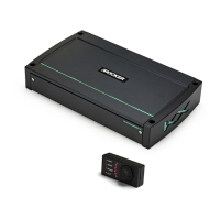
Mic Input: Connect the included microphone to the 3.5mm (1/8”) microphone input and use in conjunction
with the Auto Setup process to automatically set Time Alignment, KICKER EQ, and Output Level Matching.
Install face up to headrest, pointing as straight as possible to the roof.
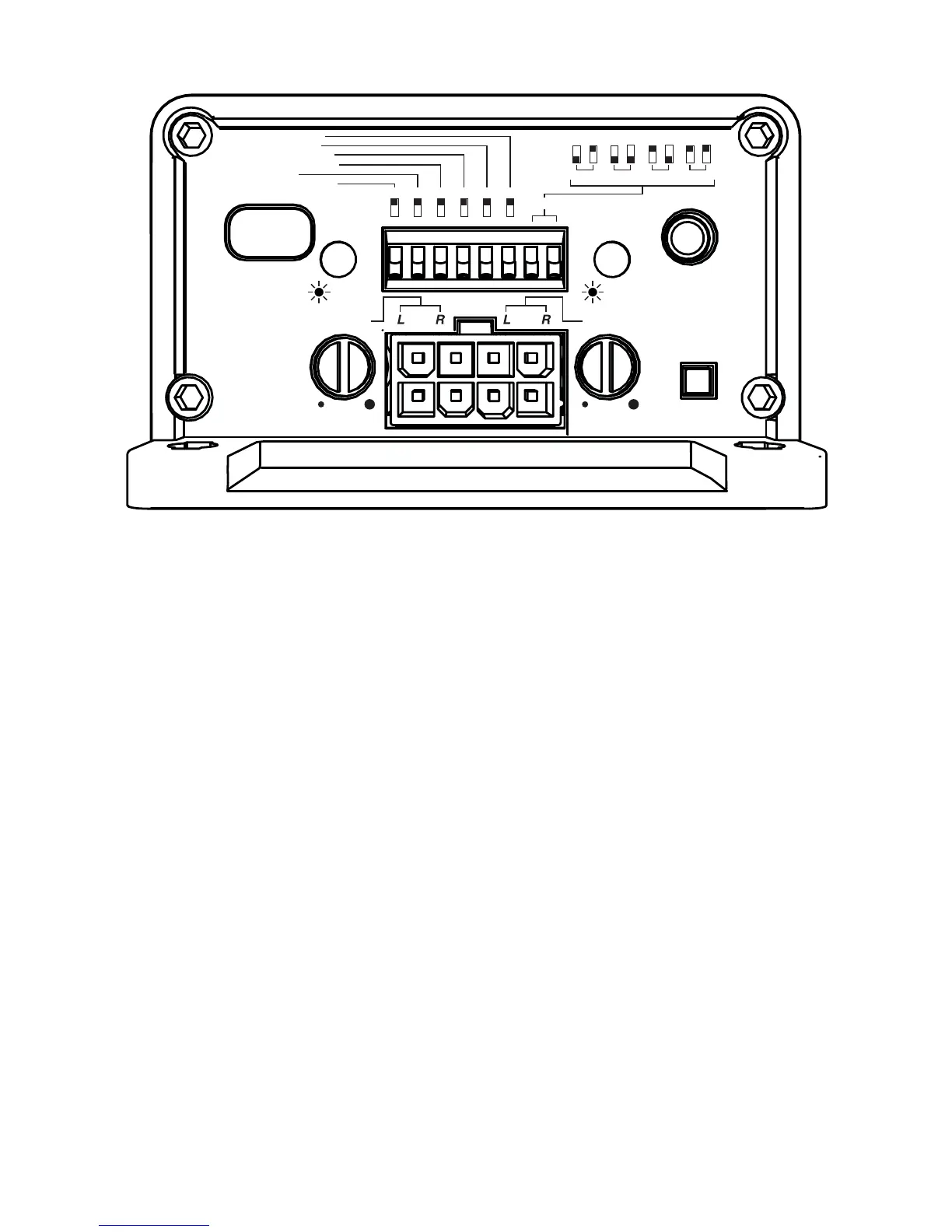
AMP1
INPUT
AMP2
MIC
INPUT
RADIO
DETECT
LIMITER LIMITER
GAIN
110
GAIN
110
HI-PASS FILTER OPTIONS
TIME DELAY
KICKER EQ
BI-AMP MODE
COMPRESSION
FADER
AUTO TURN-ON
60Hz 80Hz 120Hz OFF
DC
ON
ON DF
12V
OFF
OFF EN
DF
EN
AMP1&2
ON
OFF