3
12V
PRT PWR
battery
fuse
left rear
left front
+
–
–
–
–
+
+
+
right front
right rear
remote turn-on
(see page 6)
bare-metal
chassis ground
bare-metal
chassis ground
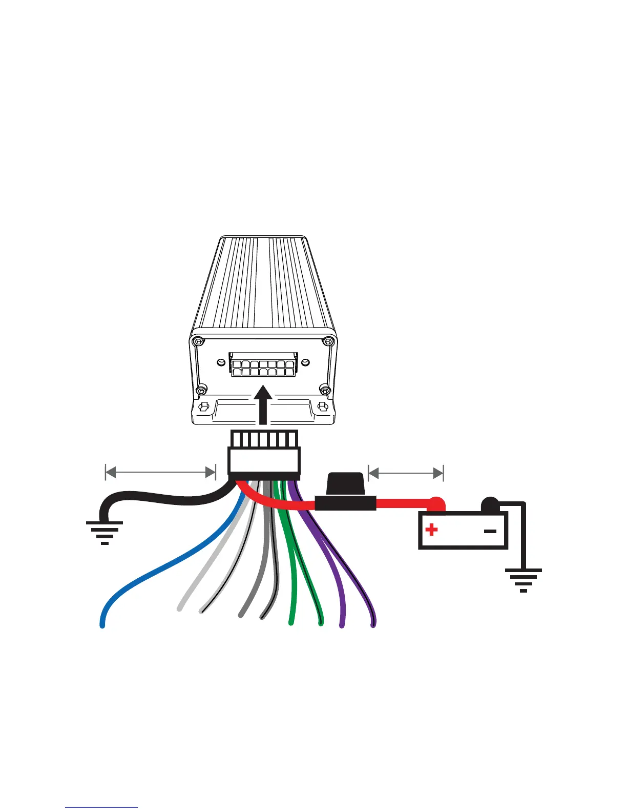
≤18”
(45cm)
≤24”
(60cm)
speaker outputs
AMP 1
AMP 2
Wiring: Disconnect the vehicle’s battery to avoid an electrical short. Then connect the ground wire to the
amplifi er. Make the ground wire short, 24” (60cm) or less, and connect it to a paint-and-corrosion-free,
solid, metal area of the vehicle’s chassis. Adding an additional ground wire of this same gauge (or larger)
between the battery’s negative post and the vehicle chassis is recommended. Keep the audio signal
cable away from factory wiring harnesses and other power wiring. If you need to cross this wiring, cross it
at a 90 degree angle.
Cut the looped red power cable located in the KEY carton and install using the 20A fuse. The fuse should
be within 18” (45cm) of the battery and in-line with the harness’ power cable, which is connected to your
amplifi er. If you ever need to remove the amplifi er from the vehicle after it has been installed, the ground
wire should be the last wire disconnected from the amplifi er--just the opposite as when you installed
it. The KEY amplifi er is capable of using the wiring directly from your head unit, but for best results it
is recommended you use power and ground wiring from the vehicle’s battery and chassis. KICKER
recommends 14 gauge wire.