1-606-235975-001 November 2002
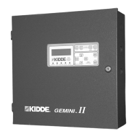
Kidde Gemini II System
When events (alarms, troubles or supervisory) occur/
become active
When events clear
When events are silenced/acknowledged
When the MCP/RHUs or RDUs are reset
When the Abort is activated
When the MCP and/or RHU releases its agent.
As mentioned earlier, current alarms and supervisory mes-
sages are viewed by pressing the ALARM SCROLL and
SUP/TBL (Supervisory/Trouble) SCROLL buttons. Once
the events clear and are no longer in alarm, you can see
the messages by selecting event log from List in the menu
system. The log contains two messages for the same event;
one message is generated when the event occurred and
the other message is generated when the condition cleared.
Viewing Lists is described in Paragraph 2-9.
The configuration log in the Main Control Panel stores con-
figuration parameters that you entered through the menu
system. Current and past configuration parameters can be
viewed through the menu system. See Paragraph 2-9 for
instructions.
1-4.7
Printed Circuit Boards
The Main Control Panel is microprocessor-based and con-
tains Flash EPROM and RAM memory as well as non-vola-
tile memory to store the Event Log and system configuration
parameters. This means these parameters are saved even
when the unit is powered down. Battery backup also pow-
ers the real-time clock in the Main Control Panel if needed.
The real-time clock is used to time stamp all messages
throughout the system.
1-4.8 Enclosures
All enclosures are NEMA Type 1. They are intended to be
used indoors in a relatively dust-free environment. The en-
closures are equipped with hinged doors that swing open
180° for accessibility.
The Main Control Panel enclosure is 18 gauge steel painted
red. A steel door is held closed by a key lock. All operator
interface switches and indicators are located behind the
locked cover. The enclosure is large enough to house two
12 Vdc, 12 AH batteries required for standby operation.
An optional dead-front enclosure is available (mandatory
in Canada). The dead front protects the user from any ex-
posed wiring. There is a hole in the front of the enclosure
which allows you access to the ALARM SCROLL and SUP/
TBL (Supervisory/Trouble) SCROLL buttons without open-
ing the door.
See Appendix F for special Canadian requirements.
1-5 REMOTE HAZARD UNIT
The Kidde Gemini II system can be expanded to include up
to seven Remote Hazard Units.
The Remote Hazard Unit is programmed from the Main
Control Panel and can be configured for global or local
operation (more on this below). Values are stored in non-
volatile (permanent) memory in the Remote Hazard Unit.
The Remote Hazard Unit communicates with the Main
Control Panel over the data network.
1-5.1 Power Supply and Battery Backup
The power supply operates from either 120 Vac 50/60 Hz
or 240 Vac 50/60 Hz. Besides powering the system, the
power supply also charges a standby battery set which pro-
vides backup in case of loss of power from the AC.
While the battery charger is capable of charging batteries
of capacity from 12 to 66 AH at 24 Vdc, the actual battery
capacity used for an application is a function of the panels
components, devices and configuration. Please refer to
Appendix A, Battery Capacity Calculations, for more de-
tails on how to preform these calculations.
The power supply includes two Auxiliary 24 Vdc power out-
puts; one is resettable and the other non-resettable. The
non-resettable Auxiliary power supply can be used to pro-
vide power to the Remote Display Units as described in
Paragraph 1-6.2.
The power supply provides a trouble signal if any of the
following conditions occur:
Loss of AC input or if AC power falls below 85% of
nominal. This causes an immediate change-over to
battery operation and a trouble signal after 30 seconds.
Detection of a ground fault.
Charger output trouble in the charger circuit.
The battery circuit is monitored and a trouble message re-
sults under the following conditions:
The battery is faulty or it was installed backwards.
The battery is disconnected.
Battery voltage falls below 18.6 V (this condition causes
the battery to disconnect and can only be cleared when
primary AC main power is restored).
1-5.2 Display
The optional display panel on the Remote Hazard Unit con-
tains five system status LEDs, a display panel for trouble
and alarm messages, and control buttons to silence the
alarm buzzer and scroll through alarm and event data. The
DISPLAY and SILENCE buttons operate in local or global
mode. The RESET button is local only.

 Loading...