7-3November 2002 06-235975-001
Kidde Gemini II System
enclosure must not be exposed to ambient temperatures
below 32°F (0°C) or above 120°F (49°C). Relative humid-
ity should not exceed 93% non-condensing @ 100°F
(36.5°C).
Position the enclosure in a readily accessible and easily
visible location about 44 inches (112 cm) from the floor in
order to place the display panel at a convenient viewing
height. Ensure there is a 1-1/2 foot clearance in front of the
enclosure for the door to swing open.
The Main Control Panel and Remote Hazard Unit enclo-
sures are designed to be surface or semi-flush mounted.
Use screws or bolts no smaller than No. 10 (3/16”) in diam-
eter to secure the enclosure to wall studs or masonry walls.
Never mount the enclosure to drywall or plaster walls with-
out securing to studs.
The Remote Display Unit has mounting screw holes on the
sides as well, and can be flush mounted between studs.
The type of hardware is at the discretion of the installer, but
must be in accordance with good electrical and safety prac-
tices. All installation wiring must adhere to NFPA 70 (NEC)
and all state and local codes.
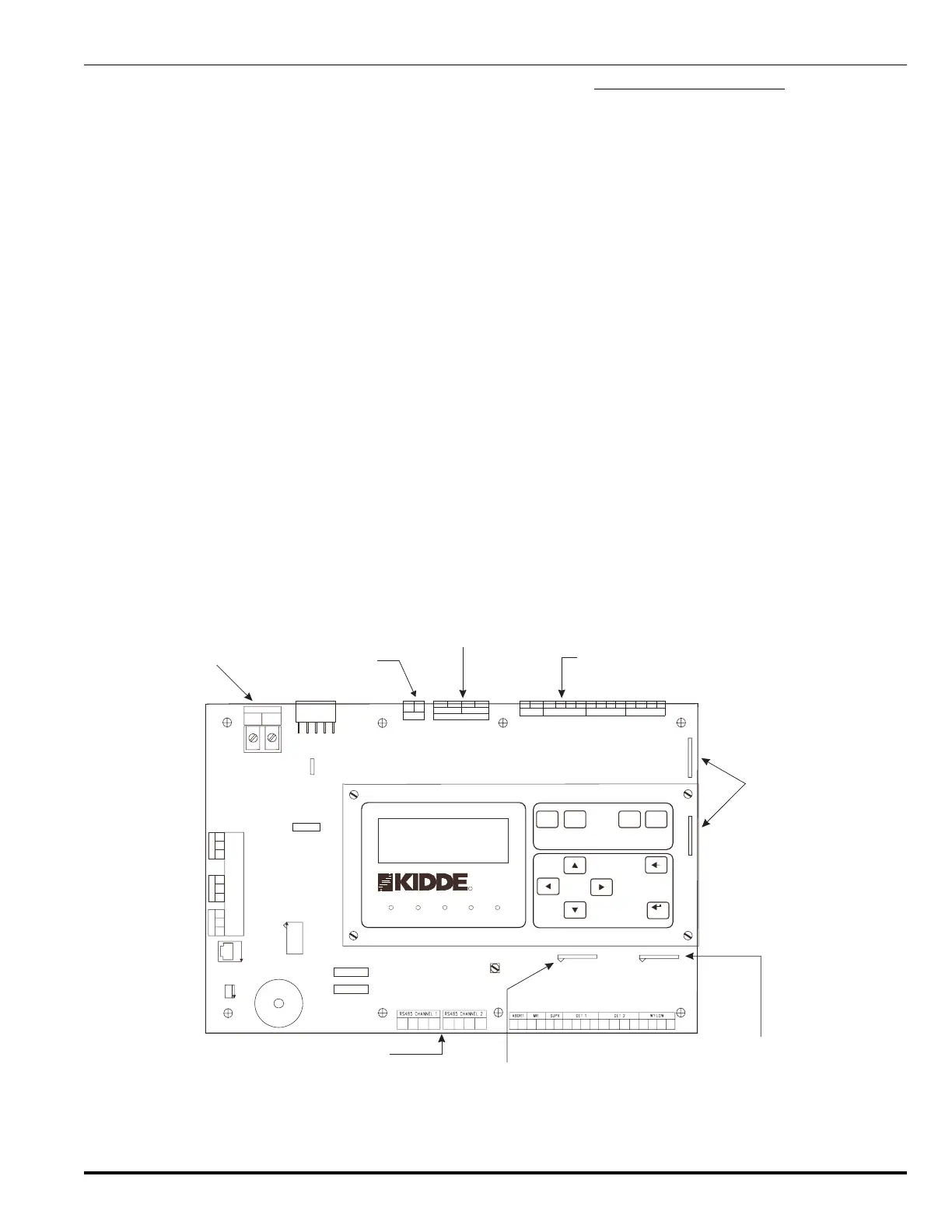
7-3.1.6 PRINTED CIRCUIT BOARDS
Figures 7-2, 7-3 and 7-4 show the layouts of the printed
circuit boards of the MCP, the RHU and the RDU respec-
tively.
7-3.2 Unit Installation Procedures
The first step in the installation procedure is to prepare sys-
tem layout and wiring drawings. The wiring drawings spe-
cific to a unit should be secured to the inside of its cabinet
after the installation is complete for future reference.
7-3.2.1 ENCLOSURE MOUNTING PROCEDURE
Once the locations of the system units i.e., the MCP, the
RHUs and RDUs is decided, the next step is to mount the
enclosures/backboxes using the following steps:
1. For the MCP and RHU, remove the Power Supply and
PCB/Display Assembly cartons from within the enclo-
sure and place them in a safe location.
2. Mount the MCP and RHU enclosures as follows:
a. Remove the front door of the enclosure. To remove
the front door, remove the ground wire, open the
door about 90° from the closed position and lift it
up until the door hinge pins clear the mating hinge
sockets on the left side of the enclosure.
b. Remove knockouts as required (taking the battery
location at the bottom of the enclosure into consid-
eration).
c. To mount against a wall, place the mounting screws
(not provided) in the wall to match the keyholes at
the back of the enclosure. Leave about ¼” of both
J4
J5
TB6
TB7
TB4
TB1000
TB5
J1
W200
W109
W101
W104
NO
C
NC
A
M
L
NO
C
NC
T
L
B
NO
C
NC
P
O
R
INTERNAL
SOUNDER
LCD
CONTRAST
VR1
W108
AC & 24V
PSU PLUG
J1001
J1000
AC MAINS INPUT
L
N
TB3
G
TB1: AC Power
TB3: 24 Vdc
output
TB6: Indicator, release and
stop valve outputs
Battery connection
Shorting links W 108 & W109,
sounder output circuit
Shorting link W104; pins 1-4 are for
waterflow input and pins 5-8 are for
the data highway
Shorting link W101,
detection input circuit
TB7: RS-485 data channel
+
-
+-+-
1+ 2+ 2- 1- 1+ 2+ 1- 1+ 2+ 2- 1-
2-
A1 B1 A2
B2
A1 B1 A2 B2
+
R2-
R2+ R1-
R1+
1- 2- 1- 2-1+ 1+2+ 2+
-
SOUNDER 1
SOUNDER 2
RELEASESTOP V
-
+
+
_
+
RESET NON-RESET
_
AUX 24 V OUT
BATT
MAIN
CONTROL
PANEL
POWER ON
ALARM
TROUBLE
SUPERVISORY
SIGNAL
SILENCED
RESET
ALARM
SCROLL
SYSTEM
CONTROLS
SIGNAL
SILENCE
SUP/TBL
SCROLL
MENU
CONTROLS
CANCEL
ACCEPT
R
R
W1000
1
2
3
Figure 7-2. Main Control Panel Printed Circuit Board