7-406-235975-001 November 2002
Kidde Gemini II System
ADDRESS
SW2
TB1
TB1000
TB3
W109
AC MAINS INPUT
L
N
TB6
J4
J5
TB7
J1
W104
W101
TB5
INTERNAL
SOUNDER
LCD
CONTRAST
VR1
J1000
J1001
W108
AC & 24V
PSU PLUG
W200
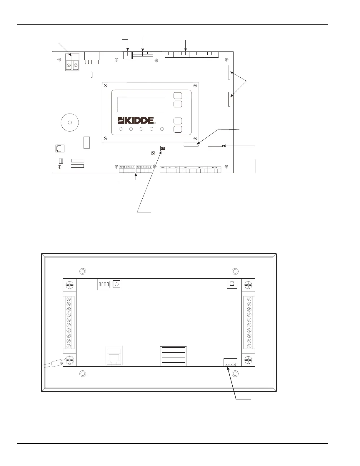
Shorting link W104; pins 1-4 are for
waterflow input and pins 5-8 are for
the data highway
Shorting link W101,
detection input circuit
TB1: AC Power
TB3: 24 Vdc
output
TB6: Indicator, release and
stop valve outputs
Shorting links W 108 & W109,
sounder output circuit
TB7: RS-485 data channel
Dip switch SW2:
network address
Battery connection
+
R2-
R2+ R1-
R1+
1- 2- 1- 2-1+ 1+2+ 2+
-
SOUNDER 1
SOUNDER 2
RELEASESTOP V
+
_
+
RESET NON-RESET
_
AUX 24 V OUT
+
BATT
-
+
-
+-+-
1+ 2+ 2- 1- 1+ 2+ 1- 1+ 2+ 2- 1-
2-
A1 B1 A2
B2
A1 B1 A2 B2
SIGNAL
SUPERVISORYPOWER ON
ALARM
UNIT
TROUBLE
SIGNAL
SUP/TBL
SCROLL
REMOTE
HAZARD
ALARM
SCROLL
CONTROLS
SYSTEM
RESET
SILENCE
SILENCED
R
R
Figure 7-3. Remote Hazard Unit Printed Circuit Board
INPUT
REL. I/P
MANUAL
+
-
ISP
+
24V OUT
ABORT
TROUBLE
-
+
PSU
+
-
24V IN
-
+
J5
J4
B
2IN
W1
Shorting Link W1
for Data Highway
CHANNEL
2 OUT
B
A
B
1IN
CHANNEL
1 OUT
CHANNEL
NOT USED
B
A
A
CHANNEL
CHASSIS
LCD
CONTRAST
VR1
A
ADDRESS
TB1
1
2
3
4
5
6
7
8
9
10
PIN #
TB2
10
9
2
5
7
8
6
4
3
PIN #
1
-
SW3
Figure 7-4. Remote Display Unit, Printed Circuit Board