1-7November 2002 06-235975-001
Kidde Gemini II System
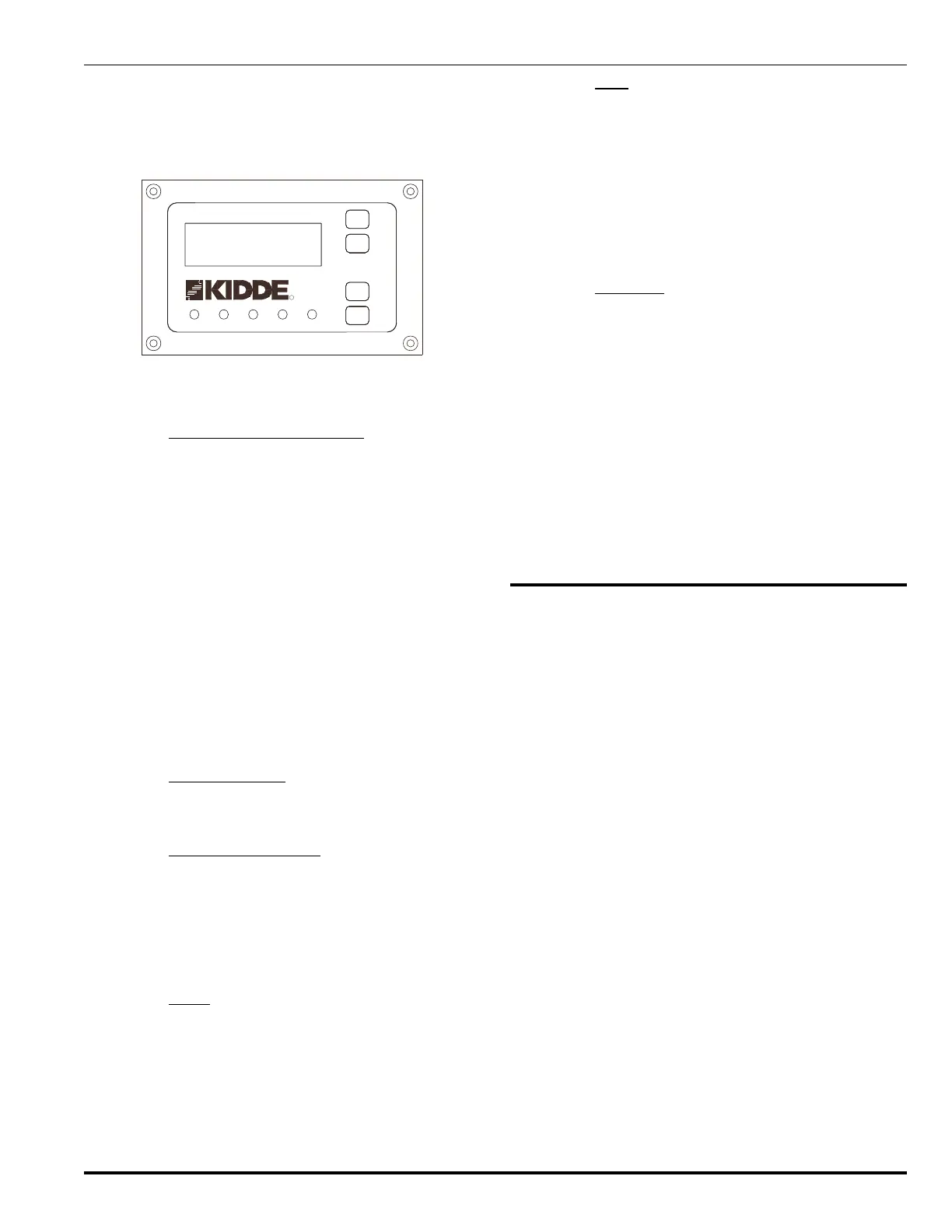
When configured for global mode, system-wide messages
and all events from all the hazards on the system are dis-
played. In local mode, only events originating in its own
hazard are displayed and silenced. Similarly, LEDs also
operate in local and global mode.
SIGNAL
SUPERVISORYPOWER ON
ALARM
UNIT
TROUBLE
SIGNAL
SUP/TBL
SCROLL
REMOTE
HAZARD
ALARM
SCROLL
CONTROLS
SYSTEM
RESET
SILENCE
SILENCED
R
R
09-17-02
ALM00 SUP0 TBL00
RHU v1.BA
LOCAL STATUS NORMAL
12:00
Figure 1-4. Remote Hazard Unit Optional
Front Panel Display
1-5.3 Single Hazard Control Block
Like the Main Control Panel, the Remote Hazard Unit con-
trols its own complete, single hazard block. It has its own
initiating (detecting) and abort input circuits as well as its
own agent release and indicating output circuits.
In the event of a communications failure, the Remote Haz-
ard Unit continues to function in a stand-alone mode, that
is, displaying local messages and monitoring hazards at
that unit.
The Remote Hazard Unit can be configured for global or
local mode. In global mode, the Remote Hazard Unit mim-
ics the Main Control Panel display. In local mode, the Re-
mote Hazard Unit displays only its own messages.
Input and output circuits are the same as the Main Control
Panel, except for the primary system relays which are MCP
applicable only. Refer to Paragraphs 1-4.3 and 1-4.4.
1-5.4 Communications
The Remote Hazard Unit connects to the data highway
through the network communications port (RS-485).
1-5.5 Printed Circuit Boards
Like the Main Control Panel, the Remote Hazard Unit also
holds event and alarm information in non-volatile memory.
The unit is microprocessor-based and contains Flash
EPROM and RAM memory as well as non-volatile memory.
The time is downloaded from the real-time clock in the Main
Control Panel.
1-5.6 Reset
The RHU can be reset either locally or remotely from the
MCP. When activated with the RESET button on the front
panel, it resets the local detector circuits for one second
and clears status memory of any events. The local proces-
sor then restarts and interrogates the input circuits for any
events.
1-5.7
Logs
Each RHU uses its volatile memory to create a Local Ac-
tive Event List. This list contains every active alarm, trouble
and supervisory event that is present at that RHU. When
any of these active events is silenced/acknowledged, that
fact is recorded in the Local Active Event List. Events are
removed from the Local Active Event List as the events
clear. If the RHU loses communications with the MCP, it
uses the contents of its Local Active Event List to control
the information displayed by itself.
1-5.8 Enclosure
Like the Main Control Panel, the Remote Hazard Unit en-
closure is 18 gauge steel painted red. The enclosure is
large enough to house two 12 Vdc, 12 AH batteries required
for 24 hours standby operation.
A steel door is held closed by a key lock. All operator inter-
face switches and indicators are located behind the locked
cover.
An optional dead-front enclosure is available (mandatory
in Canada). The dead front protects the user from any ex-
posed wiring. There is a hole in the front of the enclosure
which allows you access to the ALARM SCROLL and SUP/
TBL (Supervisory/Trouble) SCROLL buttons without open-
ing the door.
1-6 REMOTE DISPLAY UNIT
The Remote Display Unit does not monitor a hazard itself,
but displays alarm and trouble messages. ALARM SCROLL
and SUP/TBL (Supervisory/Trouble) SCROLL buttons al-
low you to scroll through the list of messages. When net-
work communications are lost with the Main Control Panel,
the display freezes and scrolling is disabled.
The Remote Display Unit can also accept manual release
and abort inputs which are then passed on to the Main Con-
trol Panel or Remote Hazard Unit to which the Remote Dis-
play Unit is assigned.
One LED provides power and communications status indi-
cation. See Paragraph 2-7 for more details.
The Kidde Gemini II System can be expanded to include
up to 16 Remote Display Units. When assigned to the Main
Control Panel or a Remote Hazard Unit, the display on the
Remote Display Unit mimics the display on the unit to which
it is assigned. It also displays any Trouble events occurring
in the Remote Display Unit itself.
If the Remote Display Unit is not assigned to the Main Con-
trol Panel or a Remote Hazard Unit, the Remote Display
Unit displays all global messages (the default mode).