1-806-235975-001 November 2002
Kidde Gemini II System
POWER
REMOTE DISPLAY UNIT
R
R
ALARM
SCROLL
SUP/TBL
SCROLL
SYSTEM
CONTROLS
09-17-02
ALM00 SUP0 TBL00
RDU v1.BA
SYSTEM STATUS NORMAL
12:00
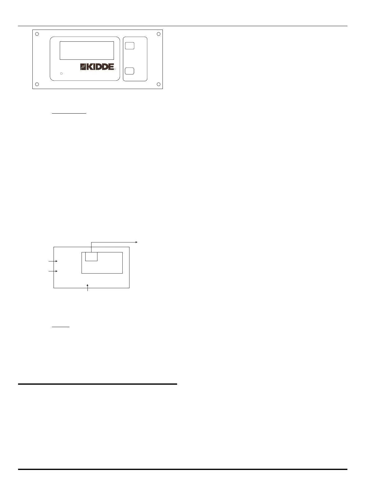
Figure 1-5. Remote Display Unit, Front Panel Display
1-6.1 Input/Output
The Remote Display Unit can also receive abort and manual
release commands from its own external abort switch and
manual pull station. Within a matter of seconds of receiv-
ing an abort signal, the Main Control Panel or Remote Haz-
ard Unit assigned to the Remote Display Unit starts the
abort sequence.
Upon receiving a manual release input signal from a pull
station, the Main Control Panel or Remote Hazard Unit as-
signed to the Remote Display Unit starts the release se-
quence to release agent or activate the sprinkler system.
A fault on the abort and manual release circuits is annunci-
ated at the Main Control Panel and all Remote Hazard Units
configured to be in global mode within 10 seconds of the
fault.
pull station
manual release
(optional)
abort
(optional)
abort station
24VDC
power from Remote
Hazard Unit or Main
Control Panel
Inputs
Output
RS485
port
data highway
to/from other units
in the system
Remote Display Unit
manual release and local abort
passed on to assigned Remote
Hazard Unit
Figure 1-6. Functional Diagram: Remote Display Unit
1-6.2 Power
The Remote Display Unit can be powered from the 24 Vdc
non-resettable auxiliary power outputs on the Main Control
Panel or Remote Hazard Unit or from a stand alone power
supply. An input is provided for monitoring power supply
status. The maximum current drawn by the Remote Dis-
play Unit is 150 mA.
1-7 COMMUNICATIONS AND THE
DATA HIGHWAY
The Main Control Panel controls all communications with
the Remote Hazard and Remote Display Units. The Main
Control Panel polls all units at least twice per second to
check that the communications link is operational and to
check the status of the units. The Main Control Panel que-
ries the Remote Hazard and Remote Display Units for
manual release and abort status, event status, alarms and
trouble messages.
The Main Control Panel also sends messages to each unit.
For example, the Main Control Panel sends system-wide
messages to Remote Hazard Units configured for global
mode. Each global RHU displays the message, updates its
LED and activates/deactivates its buzzer as appropriate.
There are two communications channels. Though they pro-
vide redundancy in case of equipment failure, both chan-
nels are used during normal operations. The Main Control
Panel transmits on one channel and receives on the other.
If the Main Control Panel has problems communicating with
one or more units, it will try to communicate on a single
channel once per minute. If normal communications are
restored, it will continue transmitting and receiving on sepa-
rate channels. If normal communications are not restored,
it will continue transmitting and receiving on the single chan-
nel.
If both channels fail, the Remote Hazard Units operate in a
stand-alone mode. They continue to monitor their own haz-
ards and will release agent if the appropriate input signals
are detected. The RESET and SILENCE buttons operate
normally.
When the communications line is restored, the Main Con-
trol Panel reestablishes communications and updates the
remote units with the current time, LED status and any
events which have been silenced.
While the MCP does not have a network address, it does
have an address which identifies it for communication pur-
poses. This address cannot be accessed or changed by
the system operator. Each Remote Hazard Unit must have
a unique address among all Remote Hazard Units. Like-
wise, a Remote Display Unit must have a unique network
address among all Remote Display Units. A Remote Dis-
play Unit and Remote Hazard Unit can have the same ad-
dress since the Main Control Panel can distinguish between
the two types of units.
Messages will refer to the Remote Hazard and Remote Dis-
play Units by their network addresses (for example, RHU#7)
unless you have assigned device tag names (assigning de-
vice tag names is described in Paragraph 7-4.8).
The network address of the Remote Hazard and Remote
Display Units are set with DIP switches on their printed cir-
cuit cards. Setting the network address is explained in Para-
graphs 7-3.2.5 and 7-3.2.6 for the RHU and RDU
respectively.
The RS-485 network operates in half-duplex mode at 9600
baud (minimum). The maximum length of the cable (in-
cluding all segments between all units) is 4,000 feet (1219
meters).