7-606-235975-001 November 2002
Kidde Gemini II System
3. Connect the positive and negative terminals of the set
of batteries to BATT+ and BATT- on TB1000 as shown
in Appendix E.
Note: Batteries should be placed in service within three
months of shipment date if stored at about 70°F,
or within one month if stored at 100°F. For longer
storage time, they require charging per
manufacturer’s specification to prevent permanent
loss of capacity.
12 Ah 12 Vdc
Battery
J4
J5
TB6
TB7
TB4
TB1 TB2 P1&P2
TB3
TB5
J1
W200
W104 W101
W109
W108
ISP RES
SW90
CPU RES
SW1
WATERFLO
W
++
SUP'V
+
ABORT
+
Man
Rel
+
DETECTOR
2
++
DETECTOR
1
++R-
24V DC
OUT
+R+
24V
IN
+
AC MAINS
INPUTLEN
N
L
NO
C
NC
A
M
L
NO
C
NC
T
L
B
NO
C
NC
V
R
F
+
SOUNDER
1
+
STOPV
+
+
SOUNDER
2
++
RELEASE
+
A
CHANNEL
1
BABA
CHANNEL
2
BAB
BATTERY
+
INTERNAL
SOUNDER
LCD
CONTRAST
VR1
-+- +
12 Ah 12 Vdc
Battery
MAIN
CONTROL
PANEL
POWERON
ALARM
TROUBLE
SUPERVISORY
SIGNAL
SILENCED
RESET
ALARM
SCROLL
SYSTEM
CONTROLS
SIGNAL
SILENCE
SUP/TBL
SCROLL
MENU
CONTROLS
CANCEL
ACCEPT
02-06-01
ALM00 SUP0 TBL00
MCP V 1.0
SYSTEM STATUSNORMAL
12:00
R
R
Figure 7-7. Backup Battery Location
7-3.2.3 CONNECTING AC POWER
AC power must be provided to the MCP and RHU internal
power supply using a 3-conductor 14 AWG cable. The AC
power cable is to be run through a one-inch conduit from a
dedicated, 15-ampere circuit breaker. The conduit must be
attached to the left side of the enclosure through one of the
upper left corner knockouts.
High voltages may be present when connecting
AC power to the MCP and RHU. Take suitable
precautions to avoid injury.
Perform the following steps to connect AC Power to the
MCP and RHUs:
1. Ensure the circuit breaker at the dedicated AC power
source is in the OFF position.
2. To ensure correct AC supply supervision, for 120 Vac
operation only, cut the leads and discard component
W200 on the MCP and RHU (see Figures 7-2 and
7-3). For 240 Vac operation, W200 must be left intact.
3. Upon completion of the initial installation steps as de-
scribed in step 2 and Paragraphs 7-3.2.4 and 7-3.2.5
for the MCP and RHU, attach the 3-conductor AC power
cable to TB1 on the printed circuit board (see Appen-
dix E) for the MCP and RHU respectively.
7-3.2.4 INSTALLING THE MAIN CONTROL PANEL
(MCP)
1. Install the MCP using the following steps:
a. Make all conduit connections into the MCP
enclosure.
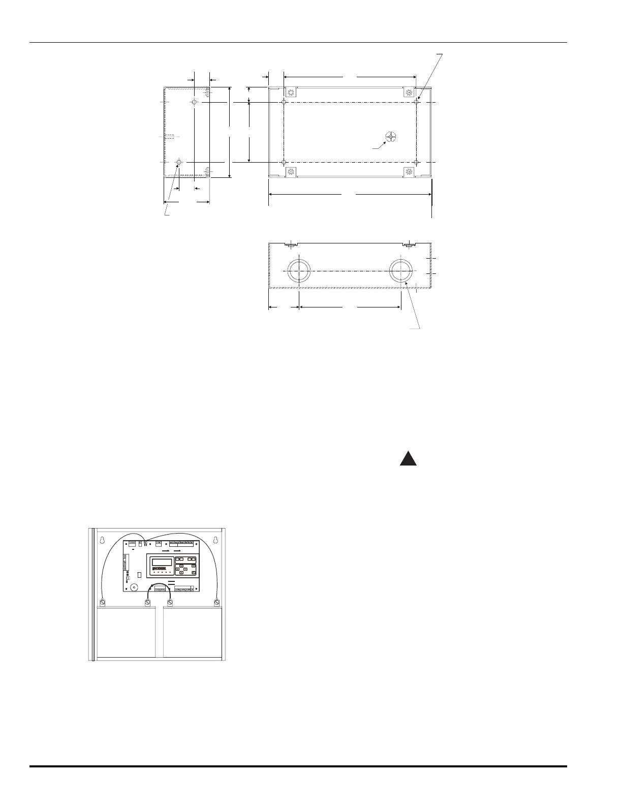
0.75”
0.75”
0.75”
8.0”
5.0”
1.5”
6.5”
2.25”
0.75”
.215 diameter - 2 holes on
each side for a total of 4.
4.45”
2.9”
1/2” - 3/4” (.875 - 1. 125) diameter
combination knockout in 2 places on
top and bottom for a total of 4.
.218 diameter - 4 holes on
back surface.
ground
Figure 7-6. Dimensions, Remote Display Unit