• When mixing models which have battery backup (i12040, i12060, i12080,
1275, 1276, 1285, 1296, PE120, PI2000, KN-COSM-IB, RF-SM-ACDC,
HD135F, KN-COB-IC, KN-COP-IC) with models without battery backup, (i1220,
1235, KN-COSM-I, 120X, SM120X,CO120X, SL177i) be advised that the mod-
els without battery backup will not respond during an AC power failure.
• The maximum wire run distance between the first and last unit in an intercon-
nected system is 1000 feet.
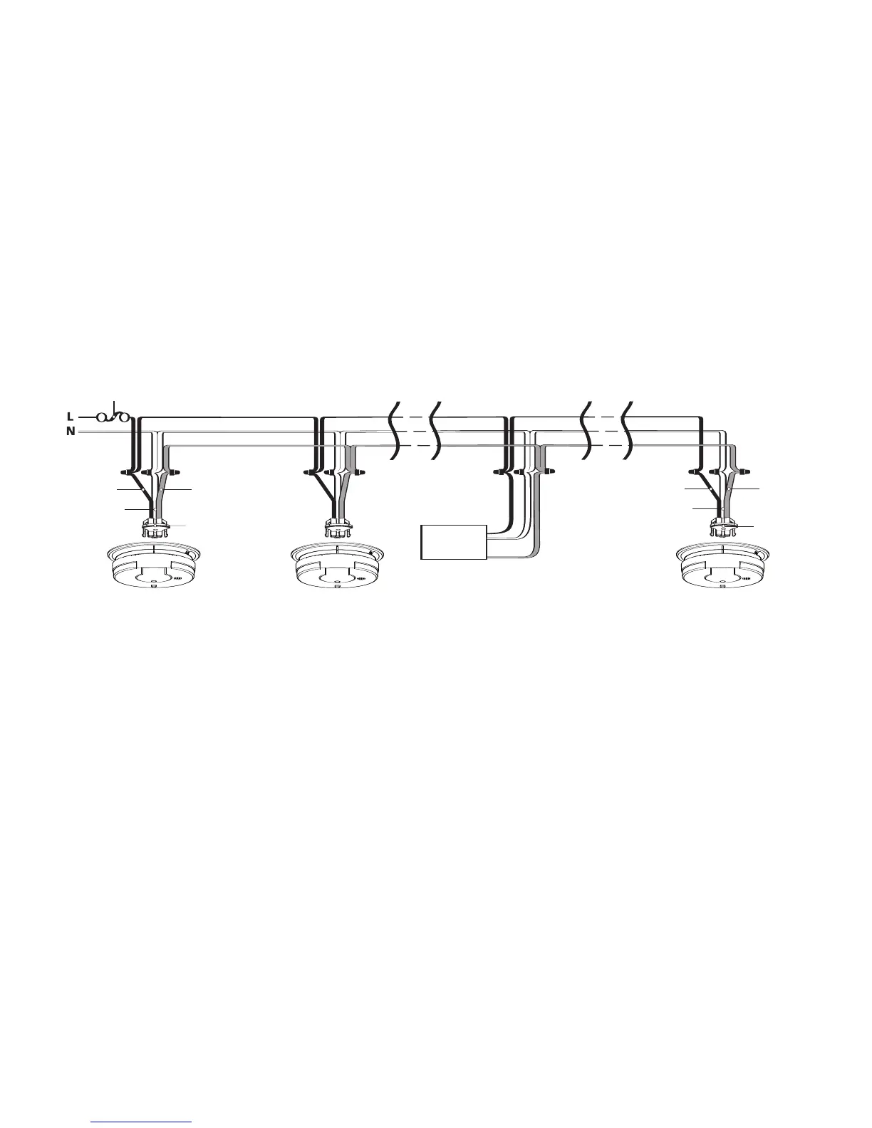
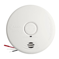
• Figure 4 illustrates interconnection wiring. Improper connection will result in
damage to the alarm, failure to operate, or a shock hazard.
• Make certain alarms are wired to a continuous (non-switched) power line.
NOTE: Use standard UL listed household wire (as required by local codes) avail-
able at all electrical supply stores and most hardware stores.
FIGURE 4 INTERCONNECT WIRING DIAGRAM
WIRES ON ALARM HARNESS CONNECTED TO
Black Hot Side of AC Line
White
Neutral Side of AC Line
Red Interconnect Lines (Red Wires) of Other
Units in the Multiple Station Set up
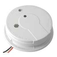
BATTERY INSTALLATION (models i12040 and i12080 only)
See MAINTENANCE (section 6) for battery installation.
CAUTION! IF THE BATTERY REMINDER FINGER(S) ARE NOT HELD DOWN
IN THE BATTERY COMP
ARTMENT BY THE BATTERY, THE BATTERY DOOR
WILL NOT CLOSE, THE AC QUICK CONNECTOR WILL NOT ATTACH TO THE
ALARM, AND THE ALARM WILL NOT ATTACH TO THE TRIM RING (SEE
SECTION 6, FIGURE 9).
MOUNTING INSTRUCTIONS
CAUTION: THIS UNIT IS SEALED. THE COVER IS NOT REMOVABLE!