Chapter 1: Fire geometry and smoke movement in buildings
VM-1 Smoke Management Application Guide 23
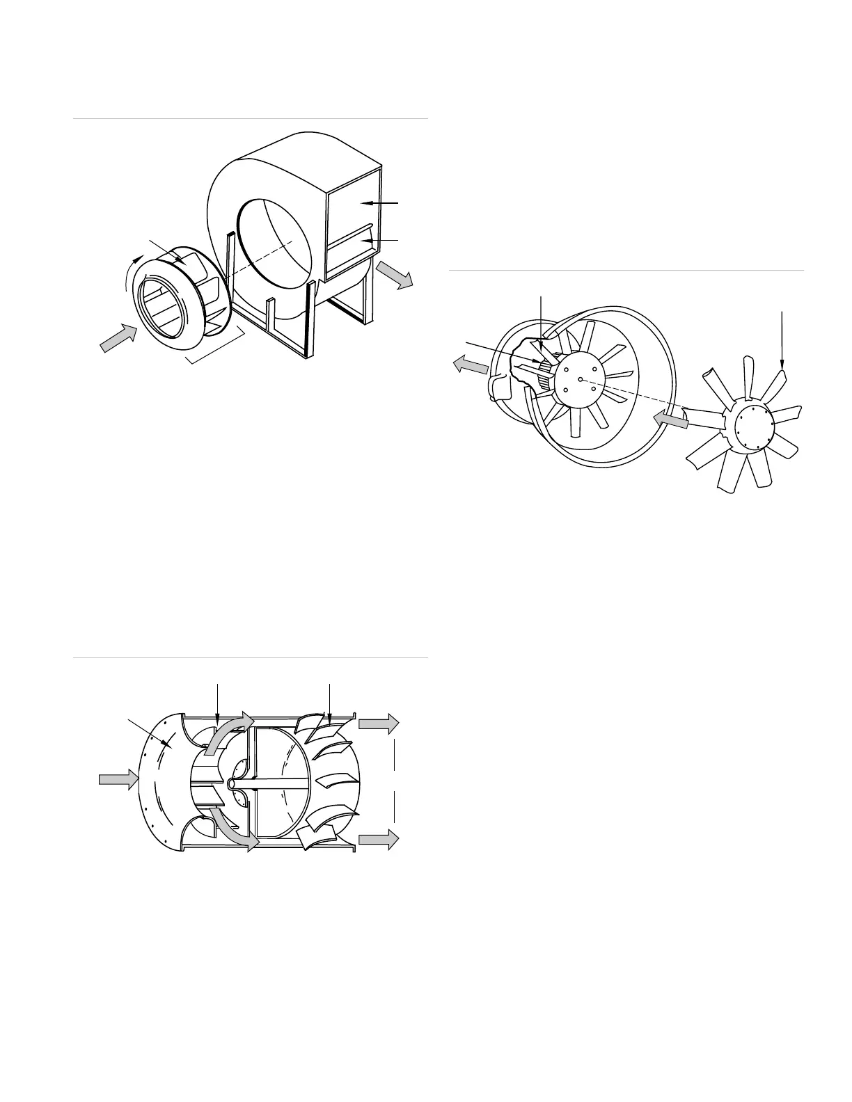
Figure 18: Centrifugal fans
(1) Outlet area
(2) Cut off
(6) Impeller rotation direction
(7) Blade fins
Airfoil fans: Airfoil fans are simply backward-curved
fans with blades of varying thickness to improve fan
efficiency. Airfoil blades are based upon the same
technology that is used to design airplane wings. Tubular
centrifugal fans (see Figure 19) are an exception to the
classification. They have single width impeller blades
and straightening vanes at the discharge. Tubular
centrifugal fans are used in low-pressure HVAC
applications, often as return air fans.
Figure 19: Tubular centrifugal fan
(1) SW centrifugal fan wheel
(2)
Straightening vanes
(5) Streamline inlet
Axial fans: Axial fans (see Figure 20) are subdivided as
propeller fans, tubeaxial fans, and vaneaxial fans. Axial
fans are designed to achieve high flow rates at low
pressures. Common uses for axial fans include kitchen
and rest room exhaust, stairwell or elevator
pressurization, and space ventilation. Propeller fans are
susceptible to adverse pressure conditions that would
include opposing wind loads from the exterior. Unlike
centrifugal fans, the backward rotation of an axial fan
normally results in backward flow at a reduced airflow
rate.
Figure 20: Axial fan
(5) Motor
Exhaust fans for smoke control are selected to operate
in the design conditions of the smoke and fire. While
dilution with ambient air can significantly cool down the
fire temperature reaching fans, there are also instances
where the direct effects of the fire will be on the smoke
control equipment.
HVAC systems with the capacity, outlets, grill locations
and flow rates are suitable for smoke control. For HVAC
systems, a means must be provided to prevent the
supply system from operating until the exhaust flow has
been established to avoid pressurization of the
fire/smoke area. In colder locations where the
introduction of outside air into the space due to
inadvertent operation or testing could damage contents,
consideration should be given towards heating the
makeup air.
Fans must reach their specified flow rate within
60 seconds and confirm the state has been reached at
the smoke control panel and the FSCS.