Chapter 1: Fire geometry and smoke movement in buildings
VM-1 Smoke Management Application Guide 27
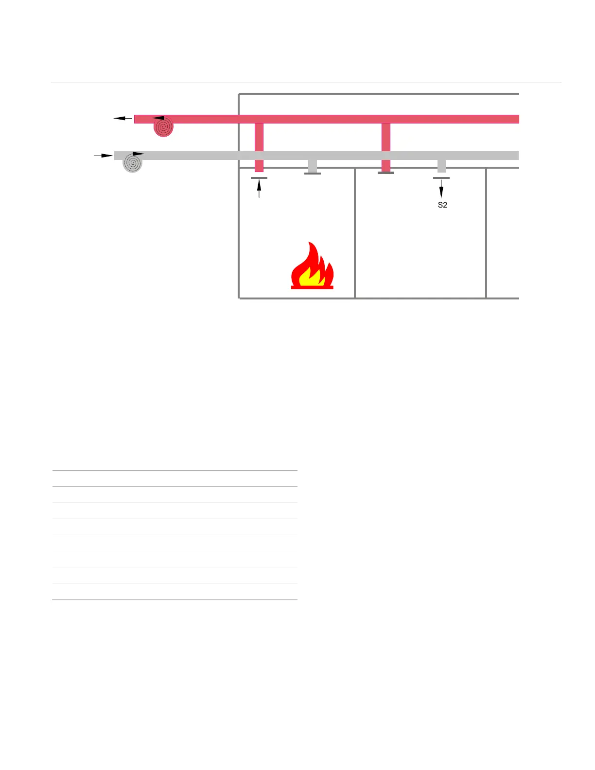
Figure 21: Smoke control using fans and dampers
Depressurization of the smoke zone is accomplished by
closing the supply damper (S1), verifying the exhaust
damper (R1) is open, and turning on the return air fan.
Pressurization of the adjacent area is accomplished by
closing the exhaust damper (R2) and opening the supply
damper (S2) while starting the supply fan.
The steps in controlling and monitoring the Figure 21
smoke control system example upon fire detection are
found in Table 2 below.
Table 2: Smoke control sequencing for Figure 21
Monitor-LED indication
Overrides normal HVAC controls
Only when Damper R1 is OPEN
Only when Damper S1 is CLOSED
Return Fan ON
Only when Damper R2 is CLOSED
Only when Damper S2 is OPEN
Supply Fan ON
The Control Sequencing in Table 1 will be discussed in
detail as it applies to a VM-1 smoke control system in
Chapters 2 and 3.
Additional reading
“Air Conditioning and Ventilating Systems,” William A.
Schmidt, NFPA Fire Protection Handbook, eighteenth
edition.
Design of Smoke Management Systems, John H. Klote
and James A. Milke.
“Emergency Movement,” Harold E. Nelson and H.E.
MacLennan, The SFPE Handbook of Fire Protection
Engineering, second edition.
Fire Alarm Signaling Systems, Richard W. Bukowski and
Robert J. O'Laughlin.
“Movement of People,” Jake Pauls, The SFPE
Handbook of Fire Protection Engineering, second
edition.
ASME/ANS A17.1 Safety Code for Elevators and
Escalators
NFPA 92A, Recommended Practice for Smoke-Control
Systems.
R1 S1
R2
Smoke zone
Adjacent smoke
control zone
Supply from outside
Exhaust to outside
Fan
Fan
Dampers