Enter the setup: dt ----- tt ----- Sr ---- SA
dt/tt
dt:the time range between each screwing process. This function will be triggered after finish
one screwing process. If user doesn’t start next screwing process in this setting time range.
The system will display "dt" until next screwing process is started. ( "01"= 1 second)
tt:All the screwing processes in this list need to be finished under this setting time range. If
user didn’t finish all the screws in this setting time range, the panel will display "tt" until all the
screwing processes are finished. ( "01"= 1 minute)
Note:
(1) When dt errors, restart the screwdriver will release from error status. If two or more error
occurs, the red light up and buzzer sounds, LED screen will display other error messages
(eg:NS);To solve another errors first and the red light will turn off , but dt continued errors.
(2) When tt error occurs, to completed all fastening process will released from tt error
condition .If an error occurs while there are other error coexist , same as dt situation .
(3) When multiple loop mode:
dt is for every one small loop (U #, #:1,2,3,4,5) , for each fastening screw time interval.
tt is for the time of one big loop (U1 ~ U #, #:2,3,4,5) , which is from U1 first start until the
end of last U # screw is fastened
(4) When the dt / tt occurs, press CLEAR to release from dt / tt , counter will return to the
original screw numbers setting of the current unit
Sr:Multiple function switch cycle SENSOR
Y:multiple cycles (SW2 = ON, SW6 = ON), when the number of fasten screws U1 are
complete then screwdriver stop until the sensor triggered (SW4 = OFF). If SW4 = ON, you
need to trigger twice before jumping to U2 ... and so on
N:multiple cycles (SW2 = ON, SW6 = ON or SW2 = ON, SW4 = ON, SW6 = ON), when the
number of fasten screw U1 are finish will automatically execute At time of that unit, then
automatically start unit 2.
Sr default:N
Note:When SW6 = ON, Sr parameter setting (Y / N) only for reference. That is, Sr is a global
variable, once SW6 = ON;Sr can set Y or N , then U2 ~ U5 SENSOR mode will follow same
setting
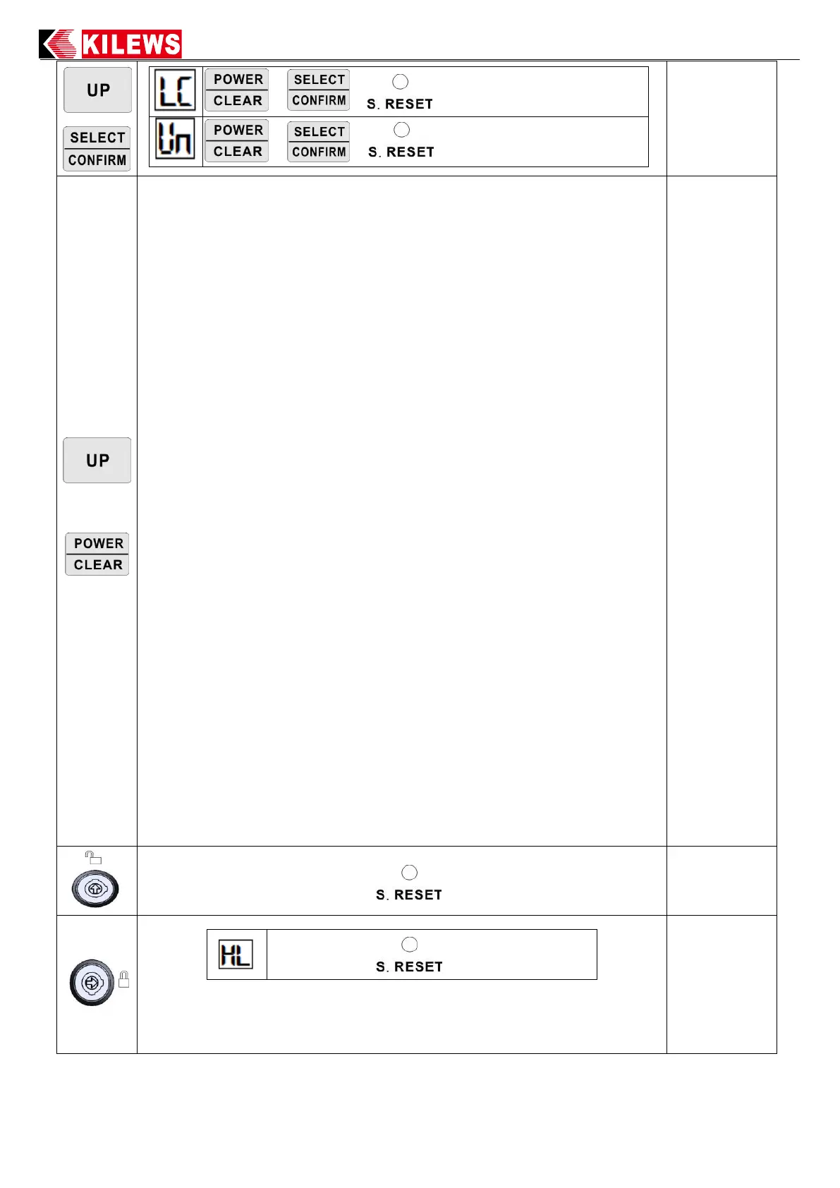
SA:When under Sensor mode, SA parameter setting only effect when the SW2 = ON, SW4 =
OFF.
The up and down button in the front panel can switch value (HI / LO).
HI:Hi Active LO:Lo Active The default value is:HI
 Loading...