Do you have a question about the Kimo DB300/1 and is the answer not in the manual?
| Accuracy | ±2% of reading ±0.1 m/s |
|---|---|
| Resolution | 0.01 m/s |
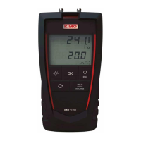
| Units | Pa, mmH2O, inWG, mbar, hPa, kPa |
| Dimensions | 140 x 80 x 32 mm |
| Weight | 190g |
| Data Logging | No |
| Operating temperature | 0°C to 50°C |
| Display | LCD |
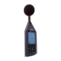
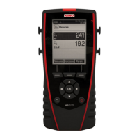
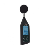
General overview of the sound level meter's components and design.
Details the instrument's screen and keyboard interface for user interaction.
Illustrates various screens displaying measurement configurations and results.
Allows adjustment of instrument settings and parameters like language and beep.
Procedure for setting the date and time on the instrument.
Configures parameters for measurements like filters and audio recording.
Sets up event coding, back-erase, and specific marking functions for measurements.
Configuration for input/output interfaces for external control and signals.
Information on remaining memory capacity and battery life.
Details instrument components, serial numbers, and firmware version.
Displays European standards, accuracy class, and calibration dates.
Adjusts display contrast and backlight levels for optimal readability.
Explains how to display and analyze short equivalent continuous levels over time.
Steps to configure integration duration and display settings for time evolution analysis.
Describes tracking and coding specific acoustic events during measurements.
Lists measurement modes compatible with event coding and back-erase functions.
Function to delete disruptive events from measurements in real-time.
Detailed process for coding noise sources or specific events during measurement.
How events are coded using the keypad or external I/O signals.
Step-by-step guide to coding events via the instrument's interface.
Assigning identification texts to coded events using the LDB300 software.
Activating the 'Particular Marking' function for specific event identification.
Using I/O signals for automatic event coding by external devices.
Function to identify short Leq data for later reminders during analysis.
Principle of particular marking for specific event identification.
How to use the screen and keypad for particular marking.
Combining particular marking with event coding for comprehensive analysis.
Performing measurements using conventional and averaging modes with data storage.
Immediate measurement acquisition and display of sound pressure levels.
Selecting weighting frequency and time constant for measurements.
Understanding the different screens that display measurement data.
Using integrator-averager mode for simultaneous data logging.
Viewing instantaneous, max/min, and session details during measurements.
Procedure to safely stop an ongoing measurement.
Saving measurement results to memory or rejecting them.
Performing Leq-St measurements with acoustic signal processing.
Initial setup for Leq-St mode, including weighting and logging time.
Starting a measurement in manual, timer, or I/O modes.
Monitoring measurement progress across different screens.
Method to stop an ongoing Leq-St measurement.
Saving or deleting measurement data after stopping.
Using the instrument as a frequency analyzer with octave band filters.
Configuring DI logging time and measurement start mode for analyzer.
Initiating a measurement in analyzer mode.
Monitoring analyzer measurements and spectral representations.
Procedure to stop an analyzer measurement.
Saving or deleting analyzer measurement data.
Measuring noise levels against NR curves for equipment analysis.
Configuring T mode or predefined duration and launch mode for NR.
Starting a measurement in NR mode.
Monitoring NR mode measurements and their spectral representations.
Stopping an NR mode measurement.
Saving or deleting NR measurement data.
Calculating equivalent continuous levels for two sound sources.
Selecting S1+S2 mode and frequency weighting for source calculation.
Measuring and calculating levels for two distinct sound sources.
Estimating the sound level of one source by excluding another.
Performing measurements to estimate individual sound source levels.
Saving or deleting results from two-source calculation measurements.
Overview of the four main measurement launch modes.
Launching measurements manually via the keypad.
Programming measurements to start and stop at specific times.
Setting up measurements to repeat daily for a specified number of times.
Instrument state when waiting for a programmed delayed measurement.
How to interrupt or cancel a delayed measurement programming.
How metrological and audio data are stored after delayed measurements.
Launching and stopping measurements using external electronic commands.
Navigating and selecting stored measurement files for review.
Viewing the configuration and results of stored measurement files.
Reading and interpreting data from L-Leq measurement files.
Reading and interpreting data from Leq-St measurement files.
Reading and interpreting data from 1/1 octave band analyzer files.
Reading and interpreting data from NR mode noise equipment measurements.
Reading and interpreting data from S1+S2 mode two-source calculation files.
Connecting the instrument to a PC for data transfer via USB.
Understanding the file naming convention and directory structure on the SD card.
Procedure to erase all data from the sound level meter's memory.
Visual representation of sound level exceeding thresholds over time.
Overview of how recording dynamic and gain are managed.
Step-by-step guide to configuring and using the audio recording feature.
Reading audio recording status and number of recordings during measurement.
Important precautions for accurate and reliable instrument use.
Guidelines for proper measurement techniques and conditions.
Procedure for calibrating the sound level meter with a suitable calibrator.
How to adjust the reference value during calibration if needed.
Basic maintenance tasks like cleaning and battery replacement.
Recommendations for regular instrument control and calibration.
Steps for replacing the instrument's battery pack.
Instructions for replacing individual batteries.
How to charge the instrument's battery via USB or adapter.
Using the AC adapter for long-period measurements.
Indicators and behavior when the measurement range is exceeded.
Information on remaining power, battery status, and mains connection.
Details on I/O interface programming for measurements.
Configuring the I/O 1 input for launching measurements.
Configuring the I/O 1 output for level detection and alarms.
Configuring the I/O 2 output for analog signal output.
Technical specifications of the class 1 microphone and windscreen.
Technical specifications of the class 2 microphone and windscreen.
Technical characteristics of the PR23 preamplifier.
Free field response plots for class 1 with A, C, Z weightings.
Free field response plots for class 2 with A, C, Z weightings.
Filter characteristics for spectral analysis by octave bands.
List of measured and displayed sound pressure level values.
Metrological specifications and features of the Class 1 DB300.
Metrological specifications and features of the Class 2 DB300.
Description of the instrument's plugs and external connections.
How to remove and attach the PR23 preamplifier.
Overview of the plugs and connections available on the instrument.
Details on the I/O interface for measurement control and output.
Information on the mini USB plug for data transfer and power.
Details on memory capacity and storage autonomy based on logging time.
Specifications for audio recording capacity, sampling, and accuracy.
Battery life and power supply options for instrument operation.
List of items included in the sound level meter package.
List of optional accessories available for purchase.
Key functionalities of the LDB23 software for data management.
Optional mode for spectral analysis using third octave bands.
Detailed explanation of the 1/3 octave band analyzer mode.
Configuring DI elementary integration time and launch mode for 1/3 octave analysis.
How to start a measurement in the 1/3 octave analyzer mode.
Monitoring measurements and reading values in the 1/3 octave analyzer mode.
Procedure to stop a 1/3 octave analyzer measurement.
Saving or deleting data from 1/3 octave analyzer measurements.
Reading and analyzing stored data from 1/3 octave measurements.