EasyManuals Logo

Kinco AX500 User Manual

Kinco AX500
23 pages
To Next Page IconTo Next Page
To Previous Page IconTo Previous Page
Page #9 background imageLoading...
Page #9 background image
Power Terminal Arrangement
No.
Name
Description
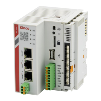
The pin diagram and definition for the coupler indicator lights are as follows:
No.
Name
Function
Description
1
24V
Power Indicator
IO Coupler and IO Module Uses
Power Supply
2
5V
Power Indicator
IO Coupler and IO Module Local
Power Supply
3
4
LINK
Communication
Indicator
FLASHES: Normal Communication
Between Modules
5
ERR
Error Indicator
ON: Module Error
6

Questions and Answers:

Question and Answer IconNeed help?

Do you have a question about the Kinco AX500 and is the answer not in the manual?

Kinco AX500 Specifications

General IconGeneral
BrandKinco
ModelAX500
CategoryController
LanguageEnglish

Related product manuals